CALEDONIAN
Professional Cable Provider
 English
Quick Contact

These cables are fire resistant, flame retardant, low smoke and halogen free, used for emergency control, power and lighting systems that need to be operational during a 1100℃ hydrocarbon fire.
IEC 60092-353
IEC 60092-360
IEC 60331-21
IEC 60332-1
IEC 60332-3-22
IEC 60754-1,2
IEC 61034-1,2
NEK 606:2016
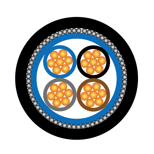
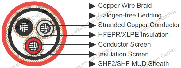
Conductors : Tinned annealed stranded compacted copper to IEC 60228 class 2 or class 5.
Insulation : Mica tape + Halogen free EPR/XLPE.
Bedding : Halogen free compound.
Armour : Tinned copper wire braid in accordance with IEC 60092-350.
Outer Sheath1 : Halogen free thermosetting compound, SHF2.
HC-fire protection : Extruded thermoplastic fire protection compound.
Taping : Lapped fire resistant tape.
Outer Sheath2 : Flame retardant halogen-free thermoplastic compound, SHF1, coloured black.
| Nominal Cross Section Area | mm² | 1.5 | 2.5 | 4 | 6 | 10 | 16 | 25 | 35 | 50 | 70 | 95 | 120 | 150 | 185 | 240 | 300 |
|---|---|---|---|---|---|---|---|---|---|---|---|---|---|---|---|---|---|
| Nominal Conductor Diameter | mm | 1.6 | 2.1 | 2.6 | 3.2 | 4.0 | 5.1 | 6.5 | 7.4 | 8.7 | 10.3 | 12.2 | 13.8 | 15.1 | 17.0 | 19.6 | 21.9 |
| Maximum DC Resistant@20℃ | Ω/km | 12.2 | 7.56 | 4.7 | 3.11 | 1.84 | 1.16 | 0.734 | 0.529 | 0.391 | 0.27 | 0.195 | 0.154 | 0.126 | 0.1 | 0.0762 | 0.0607 |
| Continuous Current Rating@45℃ 1 Core | A | 23 | 30 | 40 | 52 | 72 | 96 | 127 | 157 | 196 | 242 | 293 | 339 | 389 | 444 | 522 | 601 |
| Continuous Current Rating@45℃ 2 Core | A | 20 | 26 | 34 | 44 | 61 | 82 | 108 | 133 | 167 | 206 | 249 | 288 | 331 | 444 | 444 | 511 |
| Continuous Current Rating@45℃ 3&4 Core | A | 16 | 21 | 28 | 36 | 50 | 67 | 89 | 110 | 137 | 169 | 205 | 237 | 272 | 311 | 365 | 421 |
| Short Circuit Current 1s | A | 210 | 360 | 570 | 860 | 1430 | 2290 | 3580 | 5010 | 7150 | 10020 | 13590 | 17170 | 21460 | 26470 | 34340 | 42930 |
| Operating Voltage | KV | 0.6/1 | 0.6/1 | 0.6/1 | 0.6/1 | 0.6/1 | 0.6/1 | 0.6/1 | 0.6/1 | 0.6/1 | 0.6/1 | 0.6/1 | 0.6/1 | 0.6/1 | 0.6/1 | 0.6/1 | 0.6/1 |
Note: For more than 4-cores, the current ratings may be calculated from the following formula (IN=I1/ ³√N ), I1= Current rating for 1-core, N = Number of cores.
| Ambient Temperature Correction Factors | 35 | 40 | 45 | 50 | 55 | 60 | 65 | 70 | 75 | 80 |
|---|---|---|---|---|---|---|---|---|---|---|
| Rating Factor | 1.1 | 1.05 | 1.0 | 0.94 | 0.88 | 0.82 | 0.74 | 0.67 | 0.58 | 0.47 |
Bending Radius :20×OD (during installation); 12×OD (fixed installed)
Temperature Range : -20℃ ~ +90℃
| Construction No. of cores × Cross section | Nominal Insulation Thickness | Nominal Diameter Over Bedding | Nominal Diameter Over Sheath1 | Nominal Overall Diameter | Nominal Weight |
|---|---|---|---|---|---|
| mm² | mm | mm | mm | mm | kg/km |
| 1×50 | 1.4 | 15.0 | 18.5 | 45.5 | 2900 |
| 1×70 | 1.4 | 16.5 | 20.5 | 47.5 | 3300 |
| 1×95 | 1.6 | 18.5 | 23.0 | 50.5 | 3800 |
| 1×120 | 1.6 | 20.5 | 25.0 | 52.5 | 4260 |
| 1×150 | 1.8 | 23.0 | 27.0 | 54.5 | 4750 |
| 1×185 | 2.0 | 25.0 | 29.5 | 57.5 | 5380 |
| 1×240 | 2.2 | 28.0 | 32.5 | 66.0 | 7050 |
| 1×300 | 2.4 | 30.5 | 35.5 | 68.0 | 8000 |
| 2×1.5 | 1.0 | 10.0 | 13.0 | 40.5 | 1890 |
| 2×2.5 | 1.0 | 11.0 | 14.5 | 42.0 | 2080 |
| 3×1.5 | 1.0 | 10.5 | 14.0 | 42.0 | 2140 |
| 3×2.5 | 1.0 | 11.5 | 15.0 | 42.5 | 2200 |
| 3×4 | 1.0 | 13.0 | 16.5 | 43.0 | 2400 |
| 3×6 | 1.0 | 14.0 | 18.0 | 45.0 | 2600 |
| 3×16 | 1.0 | 18.5 | 23.0 | 50.0 | 3500 |
| 3×35 | 1.2 | 25.0 | 29.5 | 57.5 | 4840 |
| 3×70 | 1.4 | 33.0 | 39.0 | 72.0 | 8150 |
| 3×120 | 1.6 | 41.0 | 48.0 | 81.5 | 11300 |
| 3×150 | 1.8 | 46.0 | 54.5 | 88.5 | 13300 |
| 4×2.5 | 1.0 | 12.5 | 16.5 | 44.0 | 2300 |
| 4×6 | 1.0 | 15.5 | 19.5 | 47.5 | 2870 |
| 4×16 | 1.0 | 20.5 | 25.0 | 53.5 | 3830 |
| 7×1.5 | 1.0 | 14.0 | 17.5 | 44.5 | 2550 |
| 12×1.5 | 1.0 | 18.5 | 22.5 | 50.0 | 3140 |
| 27×1.5 | 1.0 | 26.5 | 31.0 | 64.5 | 5070 |
| 7×2.5 | 1.0 | 15.0 | 19.0 | 46.0 | 2760 |
| 12×2.5 | 1.0 | 20.5 | 24.5 | 52.0 | 3500 |
+852 6230 0392
Caledonian Cables
live:1cb87739a29fb08c