CALEDONIAN
Professional Cable Provider
 English
Quick Contact
A cable code of 2 letters (1. and 4.) or 4 letters is used to describe the construction.
For example :
1st Letter (Insulation) :
B : Fire resistant tape + insulation (Halogen-free)
R : Ethylene propylene rubber - EPR
T : Cross-linked polyethylene XLPE
I : Thermoplastic compound (Halogen-free)
U : Halogen-free thermosetting compound EMA or EVA
A : Fibre, tight buffered
Q : Fibre in loose tube
2nd letter (Inner Sheath) :
F : Bedding/Inner covering or taping (Halogen-free)
Y : Screen (poss. with PE or PP)
I : Thermoplastic compound (Halogen-free) SHF1
3rd letter (Armour/Screen) :
L : Aluminium (laminated to outer sheath)
X : No armour
O : Copper wire braid (Tinned or bare)
A : Strength member of yarn
C : Galvanized steel wire braid
4rd letter (Outer Sheath) :
I : Thermoplastic compound (Halogen-free), SHF1
U : Halogen-free thermosetting compound, SHF2
U : Halogen-free mud resistant thermosetting compound, SHF Mud
B* : Halogen-free mud resistant thermoplastic compound
*QFCB cables only
Additional Abbreviation for Instrumentation Cables :
(c) : Collective screen
(i) : Individual pair or triple screen
The cable shall be marked with a sheath code according to the following table, which describes the cable type and Oil/mud performance.
| Marking letters | Combinations of sheath codes describing the Oil/mud performance |
| ' no marking ' | Minimum requirements |
| E | Enhanced Oil resistant-category b |
| M | Enhanced Oil resistant-category b Mud resistant-category c |
| H | Enhanced Oil resistant-category b Hydraulic/gear Oil resistant-category d |
| H-M | Enhanced Oil resistant-category b Mud resistant-category c Hydraulic/gear Oil resistant-category d |
| NEK 606-2004 | Cables for Offshore Installations halogen-free and/or mud resistant |
| IEC 60092-350 |
Electrical installations in ships Part 350: Low-voltage shipboard power cables. (General construction and test requirements) |
| IEC 60092-360 |
Electrical installations in ships Part 351: Insulating materials for shipboard power cables |
| IEC 60092-352 |
Electrical installations in ships Part 352: Choice and installation of electric cables for low voltage power systems |
| IEC 60092-353 |
Electrical installations in ships Part 353: Single and multicore cables with extruded solid insulation for rated voltages 0,6/1 and 1,8/3 kV |
| IEC 60092-354 |
Electrical installations in ships Part 354: Single and three-core power cables with extruded solid insulation for rated voltages 6 kV up to 30 kV. |
| IEC 60092-360 |
Electrical installations in ships Part 359: Sheathing materials for shipboard power and telecommunication cables |
| IEC 60092-375 |
Electrical installations in ships Part 375: General instrumentation, control and communication cables |
| IEC 60092-376 |
Electrical installations in ships Part 376: 150/250 V cables for Control and instrumentation Circuits |
| IEC 60228 | Conductors of insulated cables |
| IEC 60331-11/12/21/25/31 | Fire resisting characteristics of electrical cables |
| IEC 60332-1/3 |
Tests on electric cables under fire condition. Part 1: Tests on a single vertical insulated wire or cable. Part 3: Test on bunched wires or cables. |
| IEC 60446 |
Basic and safety principles for man-machine interface, marking and identification. Identification of conductors by colours or alphanumerics |
| IEC 60754-1/2 | Test on gases evolved during combustion of electric cables |
| IEC 60811 | Common test methods for insulating and sheathing materials of electric cables |
| IEC 61034-1/2 |
Measurement of smoke density of electric cables burning under defined conditions. Part 1: Test apparatus Part 2: Test procedure and requirements |
The suitability of sheathing materials for use in areas in which the cables are exposed to drilling fluids is heavily dependent upon the type of fluid present. Each type of fluid contains additives which can have a deleterious effect on the sheathing material.
According to NEK 606, the mud resistant cables shall have a SHF Mud sheath that comply with the requirements in IEC 60092-360 for SHF2 and the below specified. The mud resistant cables shall be designed with sheathing compounds suitable for installation and operation in contact with MUD unless otherwise specified.
The MUD resistance test requirements for sheathing compounds SHF Mud are as follows :
| Test fluid | Temperature | Duration | Tensile Strength & Elongation At Break Variation | Volume Swell Variation | Weight Increase Variation |
|---|---|---|---|---|---|
| Mineral oil type - IRM 903 | 100℃ | 7 d | 30% | 30% | 30% |
| Calcium Bromide Brine (Waterbased) | 70℃ | 56 d | 25% | 20% | 15% |
| Carbo Sea (oil based) | 70℃ | 56 d | 25% | 20% | 15% |
All thermoset sheathed cables shall be suitable for an oil production installation. The oil resistance properties shall be demonstrated by a test according to IEC 60092-360 SHF2.
The cables shall withstand the test specified in IEC 60332-3-10, -22, -23, -24, -25. Single, earth and bonding wires shall withstand the test specified in IEC 60332-1 or IEC 60332-2.
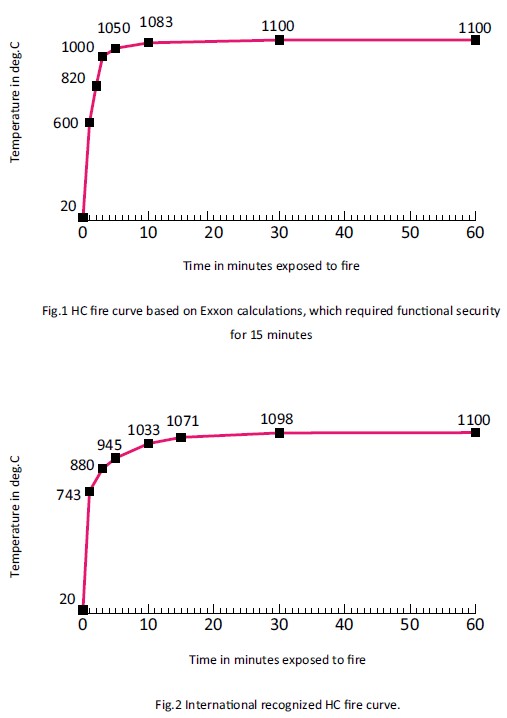
Fire resistance cables shall be tested according to IEC 60331-11, -12, -21, -25 and -31.
The purchaser shall specify which of the curves below in Figure 1 or 2 to comply with the HCF test.
The test requires no breakdown for 30 or 60 minutes when connected to operating voltage.
Time to breakdown to be considered in agreement with the customer or approval authority.
All cables shall be halogen-free according to IEC 60754-1/2.
During a cable fire smoke emission shall be kept to a minimum value of 60% according to IEC 61034-1/2.
Resistance formula :
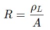
ρ = specific resistance, Ω.mm²/m
A = conductor area, mm²
L = conductor length, m
Resistance as a function of temperature :
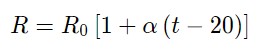
R0 = Resistance at t=20℃
t = conductor temperature, ℃
α = 0.00393 for copper
The following short circuit currents are for cables normally operating at a maximum conductor temperature of 90°C.
The theoretical temperature that arises in the conductor during a short circuit, which is used as a basis of the calculation, is 250℃. EPR and XLPE insulation are capable of withstanding short term temperatures up to 250°C.
The short circuit currents for copper conductors given in the table are values for one second,for other durations the current may be calculated from the following formula :
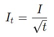
It = short ciricut current for t sec.(Amp)
I = short circuit current for one sec.(Amp)
t = short circuit duration(sec.)
The duration of the short circuit based on these assumptions should be between 0.2 sec. and 5 sec.
| Conductor area mm² | Current 1 second amperes |
|---|---|
| 1.0 | 140 |
| 1.5 | 210 |
| 2.5 | 350 |
| 4 | 560 |
| 6 | 840 |
| 10 | 1400 |
| 16 | 2240 |
| 25 | 3500 |
| 35 | 4900 |
| 50 | 7000 |
| 70 | 9800 |
| 95 | 13300 |
| 120 | 16800 |
| 150 | 21000 |
| 185 | 25900 |
| 240 | 33600 |
| 300 | 42000 |
| 400 | 56000 |
| 500 | 70000 |
| 630 | 88200 |
The reactance of a cable operating in an AC system depends on many factors, including, in particular, the axial spacing between conductors and the proximity and magnetic properties of adjacent steelwork. The former is known for multicore cable, but may vary for single core cables depending upon the spacing between them and their disposition when installed.
Reactance of cables in certain dispositions remote from steelwork is calculable and is shown.
The values are for cables with circular conductors.
The value for a sector-shaped conductor should be taken as 90% of the calculated value.
Induction for 2-, 3- and 4- conductor cables is given by the formula :
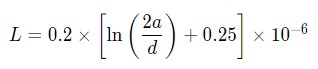
a = Axial space between conductors in mm.
d = conductor diameter in mm.
Reactance for 2-, 3- and 4-conductor cables is given by the formula :
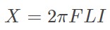
f = frequency in Hz
L = Induction in H/m
I = Conductor length in m
Induction for 2-, 3- and 4- conductor cables is given by the formula :
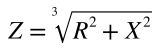
R = Resistance at operating temprature in Ω
X = Reactance in Ω
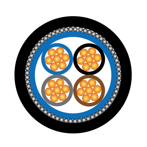
| Cable element | Colour of cores | ||
| Pair | Black | Light blue | |
| Triple | Black | Light blue | Brown |
| Pairs/triples are numbered with numbered tape or by numbers printed directly on the insulated conductors | |||
| No. of cores | Colour of cores | |||
| Single core | Off-white(grey) | |||
| Two cores | Off-white(grey) | Black | ||
| Three cores | Off-white(grey) | Black | Red | |
| Four cores | Off-white(grey) | Black | Red | Blue |
| above 4 cores | black numbers on white base | |||
| earthing core | yellow/green | |||
| Cables with a green/yellow core | |||||
| No. of cores | Colour of cores* | ||||
| Three cores | Green/yellow | Blue | Brown | ||
| Four cores** | Green/yellow | - | Brown | Black | Grey |
| Four cores | Green/yellow | Blue | Brown | Black | |
| Five cores | Green/yellow | Blue | Brown | Black | Grey |
** For certain applications only. * In this table an uninsulated concentric conductor, such as a metallic sheath, armour or screen wires, is not regarded as a core. A concentric conductor is identified by its position and, therefore, need not be identified by colour. |
|||||
| Cables without a green/yellow core | |||||
| No. of cores | Colour of cores* | ||||
| Two cores | Blue | Brown | |||
| Three cores** | - | Brown | Black | Grey | |
| Three cores | Blue | Brown | Black | ||
| Four cores | Blue | Brown | Black | Grey | |
| Five cores | Blue | Brown | Black | Grey | Black |
** For certain applications only. * In this table an uninsulated concentric conductor, such as a metallic sheath, armour or screen wires, is not regarded as a core. A concentric conductor is identified by its position and, therefore, need not be identified by colour. |
|||||
| No. of cores | Colour of cores |
| Single core | off-white insulation + black semi conducting layers |
| Three cores | off-white insulation + black semi conducting layers identified by White-Black-Red threads under and over the metallic screen on each individual core. |
| earthing core | yellow/green |
+852 6230 0392
Caledonian Cables
live:1cb87739a29fb08c