CALEDONIAN
Professional Cable Provider
 English
Quick Contact
| Cross section | cl.2 | cl.5 | Cross section | cl.2 | cl.5 |
|---|---|---|---|---|---|
| mm² | Ohm/km | Ohm/km | mm² | Ohm/km | Ohm/km |
| 1.0 | 18.2 | 20 | 70 | 0.270 | 0.277 |
| 1.5 | 12.2 | 13.7 | 95 | 0.195 | 0.210 |
| 2.5 | 7.56 | 8.21 | 120 | 0.154 | 0.164 |
| 4 | 4.70 | 5.09 | 150 | 0.126 | 0.132 |
| 6 | 3.11 | 3.39 | 185 | 0.100 | 0.108 |
| 10 | 1.84 | 1.95 | 240 | 0.0762 | 0.0817 |
| 16 | 1.16 | 1.24 | 300 | 0.0607 | 0.0654 |
| 25 | 0.734 | 0.795 | 400 | 0.0475 | 0.0495 |
| 35 | 0.529 | 0.565 | 500 | 0.0369 | 0.0391 |
| 50 | 0.391 | 0.393 | 630 | 0.0286 | 0.0292 |
| Cross section | cl.2 | cl.5 | Cross section | cl.2 | cl.5 |
|---|---|---|---|---|---|
| mm² | Ohm/km | Ohm/km | mm² | Ohm/km | Ohm/km |
| 1 | 18.1 | 19.5 | 70 | 0.268 | 0.272 |
| 1.5 | 12.1 | 13.3 | 95 | 0.193 | 0.206 |
| 2.5 | 7.41 | 7.98 | 120 | 0.153 | 0.161 |
| 4 | 4.61 | 4.95 | 150 | 0.124 | 0.129 |
| 6 | 3.08 | 3.30 | 185 | 0.0991 | 0.106 |
| 10 | 1.83 | 1.91 | 240 | 0.0754 | 0.0801 |
| 16 | 1.15 | 1.21 | 300 | 0.0601 | 0.0641 |
| 25 | 0.727 | 0.780 | 400 | 0.0470 | 0.0486 |
| 35 | 0.524 | 0.554 | 500 | 0.0366 | 0.0384 |
| 50 | 0.387 | 0.386 | 630 | 0.0283 | 0.0287 |
IEC 60228 standard provides electrical resistance of copper conductors at an ambient temperature of 20°C.
For other temperatures, correction factors are applied as below :
| Temperature (°C) | Kt |
|---|---|
| 5 | 1.064 |
| 10 | 1.042 |
| 15 | 1.020 |
| 20 | 1.000 |
| 25 | 0.980 |
| 30 | 0.962 |
| 35 | 0.943 |
| 40 | 0.926 |
| 45 | 0.909 |
| 50 | 0.893 |
| 55 | 0.877 |
| 60 | 0.862 |
| 65 | 0.847 |
| 70 | 0.833 |
| 75 | 0.820 |
| 80 | 0.806 |
| 85 | 0.794 |
| 90 | 0.781 |
| 95 | 0.769 |
| 100 | 0.758 |
| Tinned conductors | Plain conductors | |||
|---|---|---|---|---|
| Cross section | cl.2 | cl.5 | cl.2 | cl.5 |
| mm² | Ohm/km | Ohm/km | Ohm/km | Ohm/km |
| 0.5 | 41.6 | 42.5 | 40.4 | 41.4 |
| 0.75 | 26.3 | 28.3 | 26.0 | 27.6 |
| 1 | 19.3 | 21.2 | 19.2 | 20.7 |
| 1.5 | 12.9 | 145. | 12.8 | 14.1 |
| 2.5 | 8.02 | 8.71 | 7.56 | 8.47 |
| Conductor temperature | 90℃ | |||||
|---|---|---|---|---|---|---|
| Nominal cross-sectional Area | Single core | Two core | Three core & four core | |||
| mm² | A | A | A | |||
| 0.5 | 10 | 8.5 | 7 | |||
| 0.75 | 13 | 11 | 9 | |||
| 1 | 18 | 15 | 13 | |||
| 1.5 | 23 | 20 | 16 | |||
| 2.5 | 30 | 26 | 21 | |||
| 4 | 40 | 34 | 28 | |||
| 6 | 52 | 44 | 36 | |||
| 10 | 72 | 61 | 50 | |||
| 16 | 96 | 82 | 67 | |||
| 25 | 127 | 108 | 89 | |||
| 35 | 157 | 133 | 110 | |||
| 50 | 196 | 167 | 137 | |||
| 70 | 242 | 206 | 169 | |||
| 95 | 293 | 249 | 205 | |||
| 120 | 339 | 288 | 237 | |||
| 150 | 389 | 331 | 273 | |||
| 185 | 444 | 377 | 311 | |||
| 240 | 522 | 444 | 366 | |||
| 300 | 601 | 511 | 420 | |||
| d.c. | a.c. | d.c. | a.c. | d.c. | a.c. | |
| 400 | 690 | 670 | 587 | 570 | 483 | 469 |
| 500 | 780 | 720 | 663 | 612 | 546 | 504 |
| 500 | 890 | 780 | 757 | 663 | 623 | 546 |
Note
1. Maximum permissible service temperature of the conductor is 90℃.
2. The current ratings given above are based on an ambient air temperature of 45℃.
3. The current ratings given above are for 6 cables of less bunched or laid together in flat formation. When more than 6 cables are bunched or laid close together, the current ratings given above should be multiplied by correction factor 0.85.
4. For cables with more than four core cables, the current ratings are calculated by the following formula :
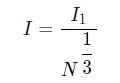
I1 : Current for single core cable
N : Number of cores
5. Correction factors for various ambient air temperature
| Maximum conductor temperature | Correction factors for ambient air temperature | |||||||||
|---|---|---|---|---|---|---|---|---|---|---|
| ℃ | 35 | 40 | 45 | 50 | 55 | 60 | 65 | 70 | 75 | 80 |
| 90 | 1.10 | 1.05 | 1.00 | 0.94 | 0.88 | 0.82 | 0.74 | 0.67 | 0.58 | 0.47 |
The short circuit currents quoted here are for cables operating normally at maximum conductor temperature of 90℃.
XLPE insulation is actually capable of withstanding short-term temperature up to 250℃.
According to ICEA P-32-382 Curves based on formula :
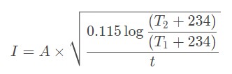
I : Short circuit current (kA)
A : Conductor area (mm²)
T1 : Operating temperature (85℃)
T2 : Short circuit temperature (250℃)
t : Short circuit duration (sec)
| Nominal Area | Short Circuit Current(kA) | |||||||||||||
|---|---|---|---|---|---|---|---|---|---|---|---|---|---|---|
| Duration of Short Circuit in Second | ||||||||||||||
| (mm²) | 0.03 | 0.05 | 0.07 | 0.1 | 0.14 | 0.2 | 0.3 | 0.4 | 0.5 | 0.6 | 0.7 | 0.8 | 0.9 | 1.0 |
| 1.5 | 1.26 | 0.98 | 0.83 | 0.69 | 0.58 | 0.49 | 0.40 | 0.35 | 0.31 | 0.28 | 0.26 | 0.24 | 0.23 | 0.22 |
| 2.5 | 2.02 | 1.56 | 1.32 | 1.10 | 0.93 | 0.78 | 0.64 | 0.55 | 0.49 | 0.45 | 0.42 | 0.39 | 0.37 | 0.35 |
| 4 | 3.25 | 2.52 | 2.13 | 1.78 | 1.50 | 1.26 | 1.03 | 0.89 | 0.80 | 0.73 | 0.67 | 0.63 | 0.59 | 0.56 |
| 6 | 4.86 | 3.77 | 3.18 | 2.66 | 2.25 | 1.88 | 1.54 | 1.33 | 1.19 | 1.09 | 1.01 | 0.94 | 0.89 | 0.84 |
| 10 | 8.19 | 6.34 | 5.36 | 4.49 | 3.79 | 3.17 | 2.59 | 2.24 | 2.01 | 1.83 | 1.70 | 1.59 | 1.50 | 1.42 |
| 16 | 12.99 | 10.06 | 8.50 | 7.11 | 6.01 | 5.03 | 4.11 | 3.56 | 3.18 | 2.90 | 2.69 | 2.52 | 2.37 | 2.25 |
| 25 | 20.6 | 15.9 | 13.5 | 11.3 | 9.5 | 8.0 | 6.5 | 5.6 | 5.0 | 4.6 | 4.3 | 4.0 | 3.8 | 3.6 |
| 35 | 28.5 | 22.1 | 18.7 | 15.6 | 13.2 | 11.1 | 9.0 | 7.8 | 7.0 | 6.4 | 5.9 | 5.5 | 5.2 | 4.9 |
| 50 | 38.6 | 29.9 | 25.3 | 21.2 | 17.9 | 15.0 | 12.2 | 10.6 | 9.5 | 8.6 | 8.0 | 7.5 | 7.1 | 6.7 |
| 70 | 55.9 | 43.3 | 36.6 | 30.6 | 25.9 | 21.6 | 17.7 | 15.3 | 13.7 | 12.5 | 11.6 | 10.8 | 10.2 | 9.7 |
| 95 | 77.5 | 60.0 | 50.7 | 42.4 | 35.9 | 30.0 | 24.5 | 21.2 | 19.0 | 17.3 | 16.0 | 15.0 | 14.1 | 13.4 |
| 120 | 97.9 | 75.8 | 64.1 | 53.6 | 45.3 | 37.9 | 31.0 | 26.8 | 24.0 | 21.9 | 20.3 | 19.0 | 17.9 | 17.0 |
| 150 | 120.3 | 93.1 | 78.7 | 65.9 | 55.7 | 46.6 | 38.0 | 32.9 | 29.5 | 26.9 | 24.9 | 23.3 | 22.0 | 20.8 |
| 185 | 150.8 | 116.8 | 98.8 | 82.6 | 69.8 | 58.4 | 47.7 | 41.3 | 36.9 | 33.7 | 31.2 | 29.2 | 27.5 | 26.1 |
| 240 | 198.3 | 153.6 | 129.8 | 108.6 | 91.8 | 76.8 | 62.7 | 54.3 | 48.6 | 44.3 | 41.0 | 38.4 | 36.2 | 34.3 |
| 300 | 248.7 | 192.6 | 162.8 | 136.2 | 115.1 | 96.3 | 78.6 | 68.1 | 60.9 | 55.6 | 51.5 | 48.2 | 45.4 | 43.1 |
| 400 | 329.3 | 255.1 | 215.6 | 180.4 | 152.5 | 127.6 | 104.1 | 90.2 | 80.7 | 73.6 | 68.2 | 63.8 | 60.1 | 57.0 |
| 500 | 401.0 | 310.6 | 262.5 | 219.6 | 185.6 | 155.3 | 126.8 | 109.8 | 98.2 | 89.7 | 83.0 | 77.7 | 73.2 | 69.5 |
| Conductor area | mm² | 1.5 | 2.5 | 4 | 6 | 10 | 25 | 35 | 50 | 70 | 95 | 120 | 150 | 185 | 240 | 300 |
|---|---|---|---|---|---|---|---|---|---|---|---|---|---|---|---|---|
| Rating factors | Ω /km | 0.135 | 0.125 | 0.117 | 0.111 | 0.103 | 0.098 | 0.097 | 0.094 | 0.091 | 0.090 | 0.088 | 0.088 | 0.088 | 0.088 | 0.087 |
The reactance of a cable operating in AC system depends on many factors, including, in particular, the axial spacing between conductors and proximity and magnetic properties of adjacent steelwork. The formar is known for multicore cable, but may vary for single core cables depending upon the spacing between them and their disposition when installed.
Reactances of cables in certain dispositions remote from steelwork are calculable and are shown. The tabulated values are for cables with circular conductors. The value for a sector- shaped conductor should be taken as 90% of the tabulated value. The value of reactance so calculated is for a supply frequency of 60Hz. For any other frequency, a correction should be made in direct proportion to the frequency.
For example at 50Hz, the reactance is 0.83 times that at 60Hz. Induction for 2-and 3- conductor cables is given by the formula :
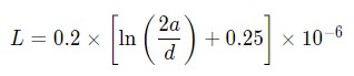
L = Inductance in H/m and phase
a = Axial space between conductor
d = Conductor diameter in mm
Reactance for 2- and 3- conductor cables is given by the formula :
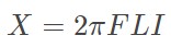
X = Reactance in ohm per phase
F = Frequency in Hz
L = Inductance in H/m and phase
I = Conductor Iength in meter
| Conductor area | mm² | 1.5 | 2.5 | 4 | 6 | 10 | 16 | 25 | 35 | 50 | 70 | 95 | 120 | 150 | 185 | 240 | 300 |
|---|---|---|---|---|---|---|---|---|---|---|---|---|---|---|---|---|---|
| Rating factors | Ω/km | 15.557 | 9.641 | 5.994 | 3.967 | 2.348 | 1.482 | 0.941 | 0.681 | 0.507 | 0.356 | 0.265 | 0.215 | 0.183 | 0.155 | 0.131 | 0.116 |
Impedance for 2, 3 & 4 conductor cables is given by the formula :
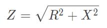
Z = Impedance in ohm per phase
R = Resistance at operating temp. in ohm per phase
X = Reactance in ohm per phase
| Nominal c.s.a mm² | K | |||||
|---|---|---|---|---|---|---|
| 3x1 cores (trefoil formation) | 2 cores | 3-4 cores | ||||
| C.d.T. c.a. cosfi 1 mV/Am | C.d.T. c.a. cosfi 0.8 mV/Am | C.d.T. c.a. cosfi 1 mV/Am | C.d.T. c.a. cosfi 0.8 mV/Am | C.d.T. c.a. cosfi 1 mV/Am | C.d.T. c.a. cosfi 0.8 mV/Am | |
| 1 | 46.4 | 37.3 | 40.1 | 32.3 | ||
| 1.5 | 31.1 | 25.0 | 26.9 | 21.7 | ||
| 2.5 | 19.3 | 15.6 | 16.7 | 13.5 | ||
| 4 | 12.0 | 9.73 | 10.4 | 8.41 | ||
| 6 | 7.93 | 6.48 | 6.860 | 5.60 | ||
| 10 | 3.51 | 2.90 | 4.69 | 3.88 | 4.059 | 3.35 |
| 16 | 2.21 | 1.86 | 2.96 | 2.48 | 2.559 | 2.15 |
| 25 | 1.40 | 1.21 | 1.87 | 1.61 | 1.620 | 1.39 |
| 35 | 1.01 | 0.891 | 1.35 | 1.19 | 1.168 | 1.03 |
| 50 | 0.747 | 0.681 | 0.998 | 0.910 | 0.864 | 0.787 |
| 70 | 0.517 | 0.494 | 0.690 | 0.660 | 0.597 | 0.571 |
| 95 | 0.374 | 0.379 | 0.500 | 0.507 | 0.432 | 0.439 |
| 120 | 0.296 | 0.316 | 0.396 | 0.422 | 0.343 | 0.365 |
| 150 | 0.244 | 0.273 | 0.282 | 0.316 | ||
| 185 | 0.195 | 0.234 | 0.225 | 0.271 | ||
| 240 | 0.151 | 0.198 | 0.174 | 0.229 | ||
| 300 | 0.122 | 0.175 | 0.142 | 0.203 | ||
The voltage drop coefficients in each circuit are given in the following table :
| Voltage | Conductor size | Voltage drop coefficient | ||||||
|---|---|---|---|---|---|---|---|---|
| mm² | 100 | 95 | 90 | 85 | 80 | 75 | 70 | |
| 250V | 0.75 | 1.00 | 0.95 | 0.90 | 0.85 | 0.80 | 0.75 | 0.70 |
| 1 | 1.00 | 0.95 | 0.90 | 0.85 | 0.80 | 0.75 | 0.70 | |
| 0.6/1KV | 1.5 | 1.00 | 0.95 | 0.90 | 0.85 | 0.80 | 0.75 | 0.71 |
| 2.5 | 1.00 | 0.95 | 0.90 | 0.86 | 0.81 | 0.76 | 0.71 | |
| 4 | 1.00 | 0.96 | 0.91 | 0.86 | 0.81 | 0.76 | 0.71 | |
| 6 | 1.00 | 0.96 | 0.91 | 0.86 | 0.81 | 0.77 | 0.72 | |
| 10 | 1.00 | 0.96 | 0.92 | 0.87 | 0.82 | 0.77 | 0.73 | |
| 16 | 1.00 | 0.97 | 0.92 | 0.88 | 0.83 | 0.76 | 0.74 | |
| 25 | 1.00 | 0.98 | 0.94 | 0.90 | 0.85 | 0.81 | 0.76 | |
| 35 | 1.00 | 0.99 | 0.95 | 0.91 | 0.87 | 0.83 | 0.78 | |
| 50 | 1.00 | 1.00 | 0.97 | 0.93 | 0.89 | 0.85 | 0.81 | |
| 70 | 1.00 | 1.02 | 1.00 | 0.97 | 0.93 | 0.90 | 0.86 | |
| 95 | 1.00 | 1.04 | 1.03 | 1.01 | 0.98 | 0.95 | 0.92 | |
| 120 | 1.00 | 1.07 | 1.06 | 1.05 | 1.03 | 1.00 | 0.97 | |
| 150 | 1.00 | 1.09 | 1.10 | 1.09 | 1.08 | 1.05 | 1.03 | |
| 185 | 1.00 | 1.13 | 1.15 | 1.15 | 1.15 | 1.13 | 1.11 | |
| 240 | 1.00 | 1.19 | 1.23 | 1.25 | 1.25 | 1.25 | 1.24 | |
| 300 | 1.00 | 1.24 | 1.31 | 1.35 | 1.36 | 1.37 | 1.37 | |
+852 6230 0392
Caledonian Cables
live:1cb87739a29fb08c