CALEDONIAN
Professional Cable Provider
 English
Quick Contact
These cables are used in control, supervisory, protection and instrumentation circuits or used as pilot cables. They commonly occur in power stations, substations or in industrial applications.
AS/NZS 2373
600/1000V
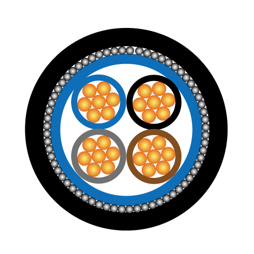
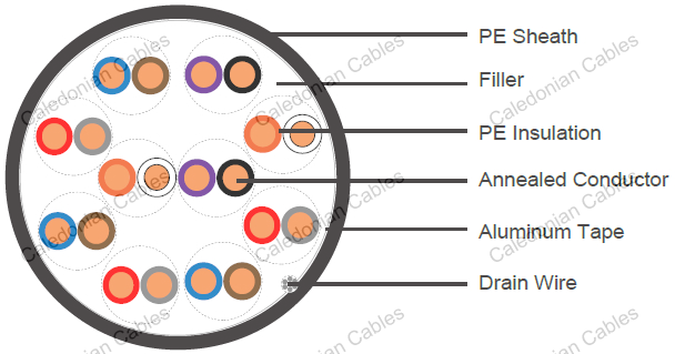
Conductor : Single wire plain annealed copper, complying with AS/NZS 1125.
Insulation : PE complying with AS/NZS 3808.
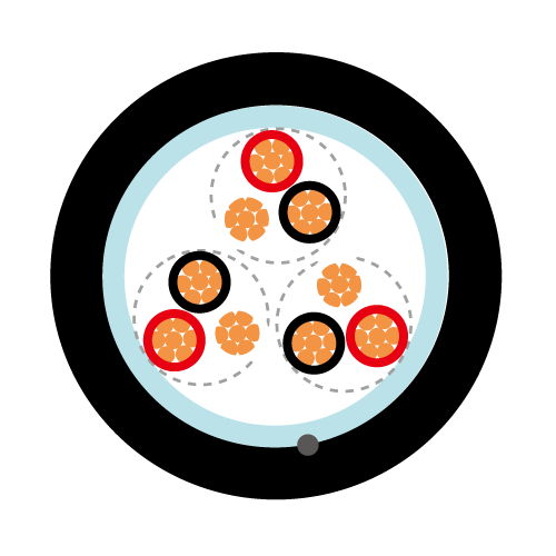
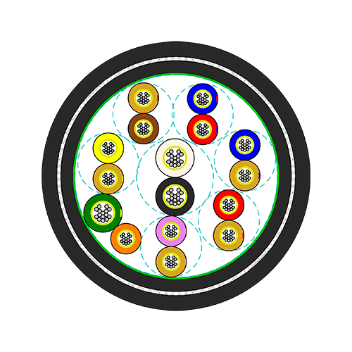
Lay-up : An adequate number of separate, identifiable lengths of lay of twisted pairs shall be used to minimize crosstalk.
Fillers and Tapes : Fillers, binder and wrapping tapes shall be of suitable non-metallic materials.
Collective screen : Copper tape or aluminum (min. thickness of 0.07mm) or aluminum/polyester tape (min. thickness of 0.023)
Drain wire : Tinned copper consisting of seven wires of at least 0.25 mm nominal diameter for aluminum tape.
Armor (optional) : Steel tape or steel wire complying with AS/NZS 5000.1
Sheath : PE, 4V-75 or HFS-75-TP complying with AS/NZS 3808.
| Nominal cross- sectional area of conductor | Nominal diameter | Insulation thickness | Sheath thickness | Maximum d.c. resistance at 20°C | |
|---|---|---|---|---|---|
| mm² | mm | mm | mm | Ω/km | |
| 0.64 | 0.90 | 0.8 | 10-pair | 1.8 | 28.3 |
| 30-pair | 1.9 | ||||
| 50-pair | 2.1 | ||||
| 100-pair | 2.4 | ||||
| 1.0 | 1.13 | 0.8 | 10-pair | 1.8 | 18.1 |
| 30-pair | 2.0 | ||||
| 50-pair | 2.2 | ||||
| 100-pair | 2.5 | ||||
| 1.27 | 1.27 | 0.8 | 10-pair | 1.8 | 14.3 |
| 30-pair | 2.1 | ||||
| 50-pair | 2.2 | ||||
| 100-pair | 2.6 | ||||
| 1.5 | 1.38 | 0.8 | 10-pair | 1.8 | 12.1 |
| 30-pair | 2.1 | ||||
| 50-pair | 2.2 | ||||
| 100-pair | 2.6 | ||||
Other size could also be provided upon request.
| Cable size | No. of pairs in centre and successive layers | |||||
|---|---|---|---|---|---|---|
| Centre | 1st | 2nd | 3rd | 4th | 5th | |
| 10-pair | 2 | 8 | - | - | - | - |
| 30-pair | 4 | 10 | 16 | - | - | - |
| 50-pair | 3 | 9 | 16 | 22 | - | - |
| 100-pair | 2 | 8 | 14 | 20 | 25 | 31 |
When the twisted pairs in the cable are identified by colors, the color coding of the pairs shall progress in sequence from the center of the cable as given in the following table. alternatively, each pair may contain a black and a white insulated core. One or both cores in each pair shall be numbered in a contrasting color. The numbering of pairs shall progress in sequence from the center of the cable.
| Centre or Layers | Insulation color | ||||||
|---|---|---|---|---|---|---|---|
| Pair 1 | Pair 2 | Pair 3 | Pair 4 | Pair 5 | Pair 6 | Last Pair | |
| 1-paircenter | Orange-white | ||||||
| 2-paircenter | Orange-white | Violet-black | |||||
| 3-paircenter | Orange-white | Red-grey | Violet-black | ||||
| 4-paircenter | Orange-white | Red-grey | Blue-brown | Violet-black | |||
| Layers | Orange-white | Red-grey | Blue-brown | Red-grey | Blue-brown | * | Violet-black |
*Pair colors shall repeat from red-grey
+852 6230 0392
Caledonian Cables
live:1cb87739a29fb08c