CALEDONIAN
Professional Cable Provider
 English
Quick Contact
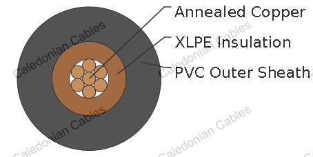
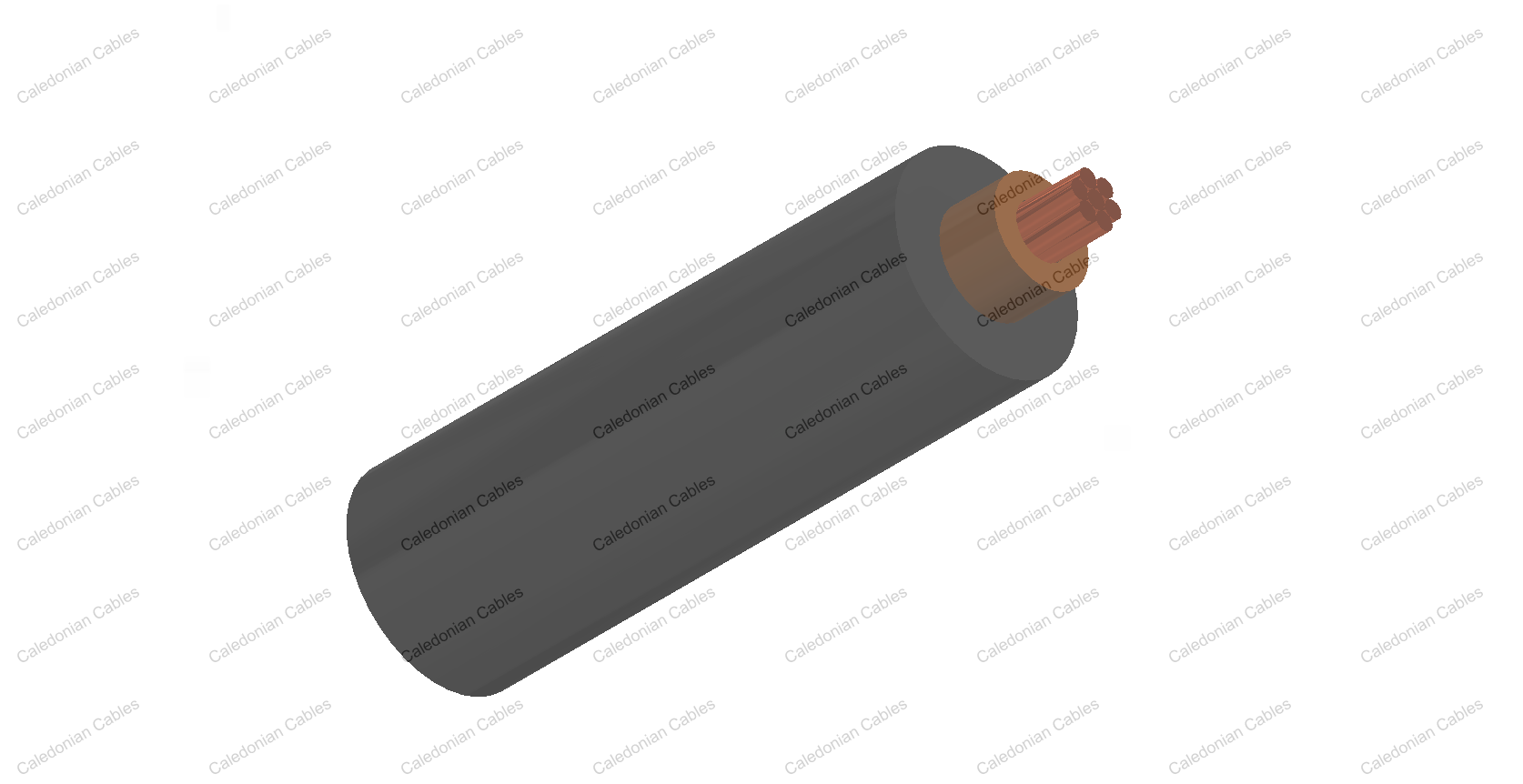
IEC 60502-1 600/1000V XLPE Insulated, PVC Sheathed Unarmoured Power Cables are mainly use in fixed installations in industrial areas, buildings and similar applications but not for burial in the ground, either directly or in ducts.
Basic design to to IEC 60502-1
| Flame Retardance (Single Vertical Wire Test) | IEC 60332-1-2 |
600/1000V
| Conductor | Plain annealed copper, stranded according to IEC 60228 class 2. |
| Insulation | XLPE according to IEC 60502-1. |
| Outer Sheath | Extruded PVC Type ST1/ST2 according to IEC 60502-1. |
| Outer Sheath Option | UV resistance, hydrocarbon resistance, oil resistance, anti rodent and anti termite properties can be offered as option. Compliance to fire performance standard (IEC 60332-1, IEC 60332-3, UL 1581, UL 1666 etc) depends on the oxygen index of the PVC compound and the overall cable design. LSPVC can also be provided upon request. |
| Insulation Colour | Brown or blue, other colours can be offered upon request. |
| Sheath Colour | Black, other colours can be offered upon request. |
| Maximum temperature range during operation | 80°C (For ST1 Sheath); 90°C (For ST2 Sheath) | ||||||||||
| Maximum short circuit temperature (5 Seconds) | 250°C | ||||||||||
| Minimum bending radius | |||||||||||
|
|||||||||||
| Conductor | FGD300 1RV-R | ||||
|---|---|---|---|---|---|
| No. of Cores x Cross Section | Class of Conductor | Nominal Insulation Thickness | Nominal Sheath Thickness | Nominal Overall Diameter | Approx. Weight |
| No.xmm2 | mm | mm | mm | kg/km | |
| 1x1.5 | 2 | 0.7 | 1.4 | 6.1 | 36 |
| 1x2.5 | 2 | 0.7 | 1.4 | 6.8 | 52 |
| 1x4.0 | 2 | 0.7 | 1.4 | 7.4 | 76 |
| 1x6.0 | 2 | 0.7 | 1.4 | 8.2 | 100 |
| 1x10 | 2 | 0.7 | 1.4 | 9.2 | 160 |
| 1x16 | 2 | 0.7 | 1.4 | 10.7 | 230 |
| 1x25 | 2 | 0.9 | 1.4 | 12.5 | 340 |
| 1x35 | 2 | 0.9 | 1.4 | 13.5 | 440 |
| 1x50 | 2 | 1 | 1.4 | 13.7 | 541 |
| 1x70 | 2 | 1.1 | 1.4 | 15.8 | 749 |
| 1x95 | 2 | 1.1 | 1.5 | 17.5 | 1000 |
| 1x120 | 2 | 1.2 | 1.5 | 19.3 | 1241 |
| 1x150 | 2 | 1.4 | 1.6 | 21.5 | 1523 |
| 1x185 | 2 | 1.6 | 1.6 | 24.7 | 1942 |
| 1x240 | 2 | 1.7 | 1.7 | 27.7 | 2514 |
| 1x300 | 2 | 1.8 | 1.8 | 30.6 | 3125 |
| 1x400 | 2 | 2 | 1.9 | 34.2 | 3967 |
| 1x500 | 2 | 2.2 | 2 | 38 | 5063 |
| 1x630 | 2 | 2.4 | 2.2 | 42.9 | 6491 |
| 1x800 | 2 | 2.6 | 2.3 | 46 | 8075 |
| 1x1000 | 2 | 2.8 | 2.4 | 63 | 9860 |
| Conductor Operating Temperature | 70°C |
| Ambient Temperature | 30°C |
| Conductor cross-sectional area |
Reference Method A (enclosed in conduit in thermally insulating wall etc) | Reference Method B (enclosed in conduit on a wall or in trunking etc) | Reference Method C (clipped direct) | Reference Method F (in free air or on a perforated cable tray horizontal or vertical etc) | Reference Method G (in free air) Spaced by one cable diameter | |||||||
|---|---|---|---|---|---|---|---|---|---|---|---|---|
| 2 cables, single-phase a.c. or d.c. | 3 or 4 cables, three-phase a.c. | 2 cables, single-phase a.c. or d.c | 3 or 4 cables, three-phase a.c. | 2 cables, single-phase a.c. or d.c. flat and touching | 3 or 4 cables, three-phase a.c. flat and touching or trefoil | 2 cables, single-phase a.c. or d.c. flat | 3 cables, three-phase a.c. flat | 3 cables, three-phase a.c. trefoil | 2 cables, single-phase a.c. or d.c. or 3 cables three-phase a.c. flat | |||
| Horizontal | Vertical | |||||||||||
| 1 | 2 | 3 | 4 | 5 | 6 | 7 | 8 | 9 | 10 | 11 | 12 | |
| mm² | A | A | A | A | A | A | A | A | A | A | A | |
| 1.5 | 19 | 17 | 23 | 20 | 25 | 23 | - | - | - | - | - | |
| 2.5 | 26 | 23 | 31 | 28 | 34 | 31 | - | - | - | - | - | |
| 4 | 35 | 31 | 42 | 37 | 46 | 41 | - | - | - | - | - | |
| 6 | 45 | 40 | 54 | 48 | 59 | 54 | - | - | - | - | - | |
| 10 | 61 | 54 | 75 | 66 | 81 | 74 | - | - | - | - | - | |
| 16 | 81 | 73 | 100 | 88 | 109 | 99 | - | - | - | - | - | |
| 25 | 106 | 95 | 133 | 117 | 143 | 130 | 161 | 141 | 135 | 182 | 161 | |
| 35 | 131 | 117 | 164 | 144 | 176 | 161 | 200 | 176 | 169 | 226 | 201 | |
| 50 | 158 | 141 | 198 | 175 | 228 | 209 | 242 | 216 | 207 | 275 | 246 | |
| 70 | 200 | 179 | 253 | 222 | 293 | 268 | 310 | 279 | 268 | 353 | 318 | |
| 95 | 241 | 216 | 306 | 269 | 355 | 326 | 377 | 342 | 328 | 430 | 389 | |
| 120 | 278 | 249 | 354 | 312 | 413 | 379 | 437 | 400 | 383 | 500 | 454 | |
| 150 | 318 | 285 | 393 | 342 | 476 | 436 | 504 | 464 | 444 | 577 | 527 | |
| 185 | 362 | 324 | 449 | 384 | 545 | 500 | 575 | 533 | 510 | 661 | 605 | |
| 240 | 424 | 380 | 528 | 450 | 644 | 590 | 679 | 634 | 607 | 781 | 719 | |
| 300 | 486 | 435 | 603 | 514 | 743 | 681 | 783 | 736 | 703 | 902 | 833 | |
| 400 | - | - | 683 | 584 | 868 | 793 | 940 | 868 | 823 | 1085 | 1008 | |
| 500 | - | - | 783 | 666 | 990 | 904 | 1083 | 998 | 946 | 1253 | 1169 | |
| 630 | - | - | 900 | 764 | 113 | 1033 | 1254 | 1151 | 1088 | 1454 | 1362 | |
| 800 | - | - | - | - | 1288 | 1179 | 1358 | 1275 | 1214 | 1581 | 1485 | |
| 1000 | - | - | - | - | 1443 | 1323 | 1520 | 1436 | 1349 | 1775 | 1671 | |
| Nominal Cross Section Area | 2 cables d.c. | 2 cables, single-phase a.c. |
3 or 4 cables, three-phase a.c. |
||||||||||||||||
|---|---|---|---|---|---|---|---|---|---|---|---|---|---|---|---|---|---|---|---|
| Ref. Methods A and B (enclosed in conduit or trunking) | Ref. Methods C, F & G(clipped direct, on trays or in free air) | Ref. Methods A & B (enclosed in conduit or trunking | Ref. Methods C, F & G (clipped direct, on trays or in free air) | ||||||||||||||||
| 1 | 2 | 3 | Cables touching 4 | Cables spaced* 5 | 6 | 7 | |||||||||||||
| mm² | mV/A/m | mV/A/m | mV/A/m | mV/A/m | mV/A/m | mV/A/m | |||||||||||||
| 1.5 | 31 | 31 | 27 | 27 | 27 | 27 | |||||||||||||
| 2.5 | 19 | 19 | 16 | 16 | 16 | 16 | |||||||||||||
| 4 | 33 | 12 | 10 | 10 | 10 | 10 | |||||||||||||
| 6 | 7.8 | 7.9 | 6.8 | 6.8 | 6.8 | 6.8 | |||||||||||||
| 10 | 4.7 | 4.7 | 4.7 | 4 | 4 | 4 | |||||||||||||
| 16 | 2.9 | 2.9 | 2.9 | 2.5 | 2.5 | 2.5 | |||||||||||||
| r | x | z | r | x | z | r | x | z | r | x | z | r | x | z | |||||
| 25 | 1.85 | 1.6 | 0.31 | 1.9 | 1.85 | 0.19 | 1.85 | 1.6 | 0.27 | 1.65 | 1.6 | 0.165 | 1.6 | 1.6 | 0.19 | 1.6 | |||
| 35 | 1.35 | 1.35 | 0.29 | 1.35 | 1.35 | 0.18 | 1.35 | 1.15 | 0.25 | 1.15 | 1.15 | 0.155 | 1.5 | 1.15 | 0.18 | 1.15 | |||
| 50 | 0.99 | 1 | 0.29 | 1.05 | 0.99 | 0.18 | 1 | 0.87 | 0.25 | 0.9 | 0.86 | 0.155 | 0.87 | 0.86 | 0.18 | 0.87 | |||
| 70 | 0.68 | 0.7 | 0.28 | 0.75 | 0.68 | 0.175 | 0.71 | 0.6 | 0.24 | 0.65 | 0.59 | 0.15 | 0.61 | 0.59 | 0.175 | 0.62 | |||
| 95 | 0.49 | 0.51 | 0.27 | 0.58 | 0.49 | 0.17 | 0.52 | 0.44 | 0.23 | 0.5 | 0.43 | 0.145 | 0.45 | 0.43 | 0.17 | 0.46 | |||
| 120 | 0.39 | 0.41 | 0.26 | 0.48 | 0.39 | 0.165 | 0.43 | 0.35 | 0.23 | 0.42 | 0.34 | 0.14 | 0.37 | 0.34 | 0.165 | 0.38 | |||
| 150 | 0.32 | 0.33 | 0.26 | 0.43 | 0.32 | 0.165 | 0.36 | 0.29 | 0.23 | 0.37 | 0.28 | 0.14 | 0.31 | 0.28 | 0.165 | 0.32 | |||
| 185 | 0.25 | 0.27 | 0.26 | 0.37 | 0.26 | 0.165 | 0.3 | 0.23 | 0.23 | 0.32 | 0.22 | 0.14 | 0.26 | 0.22 | 0.165 | 0.28 | |||
| 240 | 0.19 | 0.21 | 0.26 | 0.33 | 0.2 | 0.16 | 0.25 | 0.185 | 0.22 | 0.29 | 0.17 | 0.14 | 0.22 | 0.17 | 0.165 | 0.24 | |||
| 300 | 0.155 | 0.175 | 0.25 | 0.31 | 0.16 | 0.16 | 0.22 | 0.15 | 0.22 | 0.27 | 0.14 | 0.14 | 0.195 | 0.135 | 0.16 | 0.21 | |||
| 400 | 0.12 | 0.14 | 0.25 | 0.29 | 0.13 | 0.155 | 0.2 | 0.125 | 0.22 | 0.25 | 0.11 | 0.135 | 0.175 | 0.11 | 0.16 | 0.195 | |||
| 500 | 0.093 | 0.12 | 0.25 | 0.28 | 0.105 | 0.155 | 0.185 | 0.1 | 0.22 | 0.24 | 0.09 | 0.135 | 0.16 | 0.088 | 0.16 | 0.18 | |||
| 630 | 0.072 | 0.1 | 0.25 | 0.27 | 0.086 | 0.155 | 0.175 | 0.088 | 0.21 | 0.23 | 0.074 | 0.135 | 0.15 | 0.071 | 0.16 | 0.17 | |||
| 800 | 0.056 | - | - | - | 0.072 | 0.15 | 0.17 | - | - | - | 0.062 | 0.13 | 0.145 | 0.059 | 0.155 | 0.165 | |||
| 1000 | 0.045 | - | - | - | 0.063 | 0.15 | 0.165 | - | - | - | 0.055 | 0.13 | 0.14 | 0.05 | 0.155 | 0.165 | |||
Note: *Spacings larger than one cable diameter will result in a large voltage drop.
r = conductor resistance at operating temperature
x = reactance
z = impedance
+852 6230 0392
Caledonian Cables
live:1cb87739a29fb08c