CALEDONIAN
Professional Cable Provider
 English
Quick Contact
The cables are mainly used in power stations, mass transit underground passenger systems, airports, petrochemical plants, hotels, hospitals, and high-rise buildings. This product type is TUV approved.
Basic design adapted to IEC 60502-1
TUV Certification (Z1 17 01 98200 004)
| Flame Retardance (Single Vertical Wire Test) | IEC 60332-1 |
600/1000V
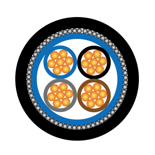
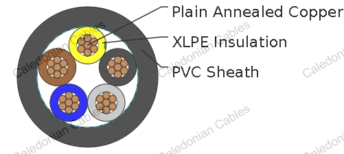
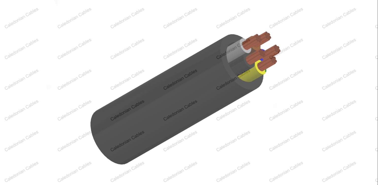
| Conductor | Annealed copper wire, stranded according to BS EN 60228 class 2. |
| Insulation | XLPE according to IEC 60502-1. |
| Inner Covering Option | Extruded PVC or polymeric compound. |
| Outer Sheath | Extruded PVC Type ST1/ST2 according to IEC 60502-1. |
| Outer Sheath Option | UV resistance, hydrocarbon resistance, oil resistance, anti rodent and anti termite properties can be offered as option. Compliance to fire performance standard (IEC 60332-1, IEC 60332-3,UL 1581, UL 1666 etc) depends on the oxygen index of the PVC compound and the overall cable design. LSPVC can also be provided upon request. |
| Insulation Colour | Two-core: Brown, blue Three-core: Brown, black, grey. Alternatively, green-and-yellow, blue, brown Four-core: Blue, brown, black, grey. Alternatively, green-and-yellow, brown, black, grey Five-core: Green-and-yellow, blue, brown, black, grey Note: Depending on their intended use, the cables might be subject to the core colour requirements specified in BS 7671 or other standards, or in statutory requirements. |
| Sheath Colour | Black, other colours can be offered upon request |
| Maximum temperature range during operation | 80°C (For ST1 Sheath); 90°C (For ST2 Sheath) |
| Maximum short circuit temperature (5 Seconds) | 250°C |
| Minimum bending radius | 12 x Overall Diameter |
| Conductor | FGD400 1RV-R | |||||
|---|---|---|---|---|---|---|
| No. of Cores x Cross Section | Class of Conductor | Nominal Insulation Thickness | Nominal Sheath Thickness |
Nominal Overall Diameter | Approx. Weight | |
| No.xmm2 | mm | mm | mm | mm | ||
| 2 Cores | ||||||
| 2x1.5 | 2 | 0.7 | 1.8 | 9.2 | 109 | |
| 2x2.5 | 2 | 0.7 | 1.8 | 10.0 | 138 | |
| 2x4.0 | 2 | 0.7 | 1.8 | 11.0 | 182 | |
| 2x6.0 | 2 | 0.7 | 1.8 | 12.0 | 234 | |
| 2x10 | 2 | 0.7 | 1.8 | 13.6 | 333 | |
| 2x16 | 2 | 0.7 | 1.8 | 15.4 | 468 | |
| 2x25 | 2 | 0.9 | 1.8 | 18.4 | 686 | |
| 2x35 | 2 | 0.9 | 1.8 | 20.6 | 926 | |
| 2x50 | 2 | 1.0 | 1.8 | 23.6 | 1269 | |
| 2x70 | 2 | 1.1 | 1.8 | 26.8 | 1699 | |
| 2x95 | 2 | 1.1 | 1.9 | 30.2 | 2269 | |
| 2x120 | 2 | 1.2 | 2.0 | 33.7 | 2853 | |
| 2x150 | 2 | 1.4 | 2.2 | 37.5 | 3539 | |
| 2x185 | 2 | 1.6 | 2.3 | 41.6 | 4329 | |
| 2x240 | 2 | 1.7 | 2.5 | 46.7 | 5607 | |
| 2x300 | 2 | 1.8 | 2.6 | 51.4 | 6892 | |
| 2x400 | 2 | 2.0 | 2.9 | 58.9 | 9202 | |
| 3 Cores | ||||||
| 3x1.5 | 2 | 0.7 | 1.8 | 9.6 | 133 | |
| 3x2.5 | 2 | 0.7 | 1.8 | 10.5 | 174 | |
| 3x4.0 | 2 | 0.7 | 1.8 | 11.6 | 236 | |
| 3x6.0 | 2 | 0.7 | 1.8 | 12.6 | 310 | |
| 3x10 | 2 | 0.7 | 1.8 | 14.4 | 452 | |
| 3x16 | 2 | 0.7 | 1.8 | 16.3 | 648 | |
| 3x25 | 2 | 0.9 | 1.8 | 19.5 | 963 | |
| 3x35 | 2 | 0.9 | 1.8 | 21.9 | 1315 | |
| 3x50 | 2 | 1.0 | 1.8 | 25.1 | 1818 | |
| 3x70 | 2 | 1.1 | 1.9 | 28.7 | 2451 | |
| 3x95 | 2 | 1.1 | 2.0 | 32.4 | 3287 | |
| 3x120 | 2 | 1.2 | 2.1 | 36.1 | 4142 | |
| 3x150 | 2 | 1.4 | 2.3 | 40.3 | 5140 | |
| 3x185 | 2 | 1.6 | 2.4 | 44.6 | 6298 | |
| 3x240 | 2 | 1.7 | 2.6 | 50.2 | 8170 | |
| 3x300 | 2 | 1.8 | 2.7 | 55.2 | 10063 | |
| 3x400 | 2 | 2.0 | 3.0 | 63.3 | 13451 | |
| 3 Cores+1 Earth Conductor | ||||||
| power conductor | earth conductor | |||||
| 3x16/10 | 2 | 0.7 | 0.7 | 1.8 | 17.5 | 793 |
| 3x25/16 | 2 | 0.9 | 0.7 | 1.8 | 21.2 | 1070 |
| 3x35/16 | 2 | 0.9 | 0.7 | 1.8 | 23.8 | 1349 |
| 3x50/25 | 2 | 1.0 | 0.9 | 1.8 | 27.5 | 1890 |
| 3x70/35 | 2 | 1.1 | 0.9 | 2.0 | 31.7 | 2660 |
| 3x95/50 | 2 | 1.1 | 1.0 | 2.1 | 35.8 | 3650 |
| 3x120/70 | 2 | 1.2 | 1.1 | 2.3 | 39.9 | 4610 |
| 3x150/70 | 2 | 1.4 | 1.1 | 2.4 | 44.6 | 5450 |
| 3x185/95 | 2 | 1.6 | 1.1 | 2.6 | 49.5 | 6680 |
| 3x240/120 | 2 | 1.7 | 1.2 | 2.8 | 55.7 | 8690 |
| 3x300/150 | 2 | 1.8 | 1.4 | 3.0 | 61.4 | 11170 |
| 3x400/185 | 2 | 1.8 | 1.6 | 3.2 | 70.4 | 11480 |
| 4 Cores | ||||||
| 4x1.5 | 2 | 0.7 | 1.8 | 10.4 | 169 | |
| 4x2.5 | 2 | 0.7 | 1.8 | 11.3 | 220 | |
| 4x4.0 | 2 | 0.7 | 1.8 | 12.5 | 297 | |
| 4x6.0 | 2 | 0.7 | 1.8 | 13.7 | 392 | |
| 4x10 | 2 | 0.7 | 1.8 | 15.7 | 585 | |
| 4x16 | 2 | 0.7 | 1.8 | 17.8 | 851 | |
| 4x25 | 2 | 0.9 | 1.8 | 21.5 | 1200 | |
| 4x35(S) | 2 | 0.9 | 1.8 | 24.1 | 1600 | |
| 4x50(S) | 2 | 1.0 | 1.8 | 27.8 | 2200 | |
| 4x70(S) | 2 | 1.1 | 2.0 | 32.0 | 3050 | |
| 4x95(S) | 2 | 1.1 | 2.1 | 36.1 | 4070 | |
| 4x120(S) | 2 | 1.2 | 2.3 | 40.2 | 5915 | |
| 4x150(S) | 2 | 1.4 | 2.4 | 44.9 | 6350 | |
| 4x185(S) | 2 | 1.6 | 2.6 | 49.8 | 7890 | |
| 4x240(S) | 2 | 1.7 | 2.8 | 56.0 | 10400 | |
| 4x300(S) | 2 | 1.8 | 3.0 | 61.7 | 12810 | |
| 4x400(S) | 2 | 2.0 | 3.2 | 70.7 | 15869 | |
| (S) - Sectoral Stranded Conductors | ||||||
| 5 Cores | ||||||
| 5x1.5 | 2 | 0.7 | 1.8 | 11.6 | 205 | |
| 5x2.5 | 2 | 0.7 | 1.8 | 12.8 | 265 | |
| 5x4.0 | 2 | 0.7 | 1.8 | 14.3 | 360 | |
| 5x6.0 | 2 | 0.7 | 1.8 | 15.8 | 478 | |
| 5x10 | 2 | 0.7 | 1.8 | 18.3 | 720 | |
| 5x16 | 2 | 0.7 | 1.8 | 21.2 | 1059 | |
| 5x25 | 2 | 0.9 | 1.8 | 25.8 | 1620 | |
| 5x35 | 2 | 0.9 | 1.8 | 28.9 | 2164 | |
| 5x50 | 2 | 1.0 | 2.1 | 33.6 | 2924 | |
| 5x70 | 2 | 1.1 | 2.2 | 39.2 | 4130 | |
| 5x95 | 2 | 1.1 | 2.4 | 44.8 | 5618 | |
| 5x120 | 2 | 1.2 | 2.5 | 49.8 | 7039 | |
| 5x150 | 2 | 1.4 | 2.7 | 55.5 | 8655 | |
| 5x185 | 2 | 1.6 | 2.9 | 62.1 | 10833 | |
| 5x240 | 2 | 1.7 | 3.1 | 70.1 | 14091 | |
| 7 Cores | ||||||
| 7x1.5 | 2 | 0.7 | 1.8 | 12.4 | 225 | |
| 7x2.5 | 2 | 0.7 | 1.8 | 13.8 | 303 | |
| 7x4.0 | 2 | 0.7 | 1.8 | 15.5 | 422 | |
| 10 Cores | ||||||
| 10x1.5 | 2 | 0.7 | 1.8 | 15.6 | 325 | |
| 10x2.5 | 2 | 0.7 | 1.8 | 17.5 | 426 | |
| 10x4.0 | 2 | 0.7 | 1.8 | 19.7 | 597 | |
| 12 Cores | ||||||
| 12x1.5 | 2 | 0.7 | 1.8 | 16.2 | 370 | |
| 12x2.5 | 2 | 0.7 | 1.8 | 18.1 | 489 | |
| 12x4.0 | 2 | 0.7 | 1.8 | 20.3 | 690 | |
| 19 Cores | ||||||
| 19x1.5 | 2 | 0.7 | 1.8 | 19.0 | 516 | |
| 19x2.5 | 2 | 0.7 | 1.8 | 21.3 | 725 | |
| 19x4.0 | 2 | 0.7 | 1.8 | 24.0 | 1037 | |
| 27 Cores | ||||||
| 27x1.5 | 2 | 0.7 | 1.8 | 22.7 | 712 | |
| 27x2.5 | 2 | 0.7 | 1.8 | 25.5 | 1004 | |
| 27x4.0 | 2 | 0.7 | 1.8 | 28.8 | 1445 | |
| 37 Cores | ||||||
| 37x1.5 | 2 | 0.7 | 1.8 | 25.5 | 941 | |
| 37x2.5 | 2 | 0.7 | 1.8 | 28.7 | 1334 | |
| 37x4.0 | 2 | 0.7 | 1.8 | 32.5 | 1932 | |
| 48 Cores | ||||||
| 48x1.5 | 2 | 0.7 | 1.8 | 29.0 | 1186 | |
| 48x2.5 | 2 | 0.7 | 1.9 | 32.9 | 1706 | |
| 48x4.0 | 2 | 0.7 | 1.9 | 37.3 | 2479 | |
Note: Other conductor sizes & core configurations are available upon request.
| Conductor Operating Temperature | 90°C |
| Ambient Temperature | 30°C |
| Conductor cross- sectional area | Reference Method A (enclosed in conduit in thermally insulating wall etc) |
Reference Method B (enclosed in conduit on a wall or in trunking etc) |
Reference Method C (clipped direct) |
Reference Method E (free air or on a perforated cable tray etc. horizontal or vertical) |
||||
|---|---|---|---|---|---|---|---|---|
| 1 two-core cable, singlephase a.c. or d.c. |
1 three- or four-core cable, three -phase a.c. |
1 two-core cable, singlephase a.c. or d.c. |
1 three- or four-core cable, three -phase a.c. |
1 two-core cable, singlephase a.c. or d.c. |
1 three- or four-core cable, three -phase a.c. |
1 two-core cable, singlephase a.c. or d.c. |
1 three- or four-core cable, three -phase a.c. |
|
| 1 | 2 | 3 | 4 | 5 | 6 | 7 | 8 | 9 |
| mm2 | A | A | A | A | A | A | A | A |
| 1.5 | 18.5 | 16.5 | 22 | 19.5 | 24 | 22 | 26 | 23 |
| 2.5 | 25 | 22 | 30 | 26 | 33 | 30 | 36 | 32 |
| 4.0 | 33 | 30 | 40 | 35 | 45 | 40 | 49 | 42 |
| 6.0 | 42 | 38 | 51 | 44 | 58 | 52 | 63 | 54 |
| 10 | 57 | 51 | 69 | 60 | 80 | 71 | 86 | 75 |
| 16 | 76 | 68 | 91 | 80 | 107 | 96 | 115 | 100 |
| 25 | 99 | 89 | 119 | 105 | 138 | 119 | 149 | 127 |
| 35 | 121 | 109 | 146 | 128 | 171 | 147 | 185 | 158 |
| 50 | 145 | 130 | 175 | 154 | 209 | 179 | 225 | 192 |
| 70 | 183 | 164 | 221 | 194 | 269 | 229 | 289 | 246 |
| 95 | 220 | 197 | 265 | 233 | 328 | 278 | 352 | 298 |
| 120 | 253 | 227 | 305 | 268 | 382 | 322 | 410 | 346 |
| 150 | 290 | 259 | 334 | 300 | 441 | 371 | 473 | 399 |
| 185 | 329 | 295 | 384 | 340 | 506 | 424 | 542 | 456 |
| 240 | 386 | 346 | 459 | 398 | 599 | 500 | 641 | 538 |
| 300 | 442 | 396 | 532 | 455 | 693 | 576 | 741 | 621 |
| 400 | - | - | 625 | 536 | 803 | 667 | 865 | 741 |
| Nominal Cross Section Area | Two-core cable d.c. | Two-core cable, single-phase a.c. | Three- or four-core cable, three-phase a.c. | ||||
|---|---|---|---|---|---|---|---|
| 1 | 2 | 3 | 4 | ||||
| mm2 | mV/A/m | mV/A/m | mV/A/m | ||||
| 1.5 | 31 | 31 | 27 | ||||
| 2.5 | 19 | 19 | 16 | ||||
| 4.0 | 12 | 12 | 10 | ||||
| 6.0 | 7.9 | 7.9 | 6.8 | ||||
| 10 | 4.7 | 4.7 | 4.0 | ||||
| 16 | 2.9 | 2.9 | 2.5 | ||||
| r | x | z | r | x | z | ||
| 25 | 1.85 | 1.85 | 0.160 | 1.90 | 1.60 | 0.140 | 1.65 |
| 35 | 1.35 | 1.35 | 0.155 | 1.35 | 1.15 | 0.135 | 1.15 |
| 50 | 0.98 | 0.99 | 0.155 | 1.00 | 0.86 | 0.135 | 0.87 |
| 70 | 0.67 | 0.67 | 0.150 | 0.69 | 0.59 | 0.130 | 0.60 |
| 95 | 0.49 | 0.50 | 0.150 | 0.52 | 0.43 | 0.130 | 0.45 |
| 120 | 0.39 | 0.40 | 0.145 | 0.42 | 0.34 | 0.130 | 0.37 |
| 150 | 0.31 | 0.32 | 0.145 | 0.35 | 0.28 | 0.125 | 0.30 |
| 185 | 0.25 | 0.26 | 0.145 | 0.29 | 0.22 | 0.125 | 0.26 |
| 240 | 0.195 | 0.200 | 0.140 | 0.24 | 0.175 | 0.125 | 0.21 |
| 300 | 0.155 | 0.160 | 0.140 | 0.21 | 0.140 | 0.120 | 0.185 |
| 400 | 0.120 | 0.130 | 0.140 | 0.190 | 0.115 | 0.120 | 0.165 |
Note: *Spacings larger than one cable diameter will result in a large voltage drop.
r = conductor resistance at operating temperature
x = reactance
z = impedance
+852 6230 0392
Caledonian Cables
live:1cb87739a29fb08c