CALEDONIAN
Professional Cable Provider
 English
Quick Contact
The cables are mainly used in power stations, mass transit underground passenger systems, airports, petrochemical plants, hotels, hospitals, and high-rise buildings. This product type is TUV approved.
Basic design adapted to IEC 60502-1
TUV Certification (Z1 17 01 98200 004)
| Flame Retardance (Single Vertical Wire Test) | IEC 60332-1 |
600/1000V
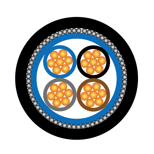
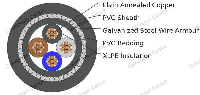
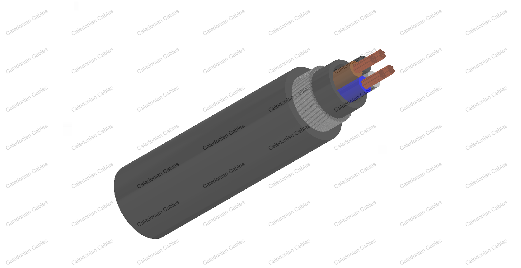
| Conductor | Annealed copper wire, stranded according to IEC 60228 class 2. |
| Insulation | XLPE according to IEC 60502-1. |
| Inner Covering | Extruded PVC or polymeric compound. |
| Armouring | Galvanized steel wire |
| Outer Sheath | Extruded PVC Type ST1/ST2 according to IEC 60502-1. |
| Outer Sheath Option | UV resistance, hydrocarbon resistance, oil resistance, anti rodent and anti termite properties can be offered as option. Compliance to fire performance standard (IEC 60332-1, IEC 60332-3, UL 1581, UL 1666 etc) depends on the oxygen index of the PVC compound and the overall cable design. LSPVC can also be provided upon request. |
| Insulation Colour | Two-core: Brown, blue Three-core: Brown, black, grey Four-core: Blue, brown, black, grey Five-core: Green-and-yellow, blue, brown, black, grey Other colours can be offered upon request. |
| Sheath Colour | Black, other colours can be offered upon request. |
| Maximum temperature range during operation | 80°C (For ST1 Sheath); 90°C (For ST2 Sheath) |
| Maximum short circuit temperature (5 Seconds) | 250°C |
| Minimum bending radius | 12 x Overall Diameter |
| Conductor | FGD400 1RVMV-R | |||||||
|---|---|---|---|---|---|---|---|---|
| No. of Cores × Cross Section | Class of Conductor | Nominal Insulation Thickness | Nominal Inner Covering Thickness | Nominal Armour Wire Diameter | Nominal Sheath Thickness | Nominal Overall Diameter | Approx. Weight | |
| No. × mm² | mm | mm | mm | mm | kg/km | |||
| 2 Cores | ||||||||
| 2x1.5 | 2 | 0.7 | 1.0 | 0.9 | 1.8 | 13.2 | 325 | |
| 2x2.5 | 2 | 0.7 | 1.0 | 0.9 | 1.8 | 14.0 | 372 | |
| 2x4.0 | 2 | 0.7 | 1.0 | 0.9 | 1.8 | 15.1 | 438 | |
| 2x6.0 | 2 | 0.7 | 1.0 | 1.25 | 1.8 | 17.1 | 645 | |
| 2x10 | 2 | 0.7 | 1.0 | 1.25 | 1.8 | 19.0 | 806 | |
| 2x16 | 2 | 0.7 | 1.0 | 1.25 | 1.8 | 21.1 | 1015 | |
| 2x25 | 2 | 0.9 | 1.0 | 1.6 | 1.8 | 25.2 | 1517 | |
| 2x35 | 2 | 0.9 | 1.0 | 1.6 | 1.8 | 27.5 | 1830 | |
| 2x50 | 2 | 1.0 | 1.0 | 1.6 | 1.9 | 30.8 | 2259 | |
| 2x70 | 2 | 1.1 | 1.0 | 2.0 | 2.0 | 35.8 | 3182 | |
| 2x95 | 2 | 1.1 | 1.2 | 2.0 | 2.1 | 40.2 | 4022 | |
| 2x120 | 2 | 1.2 | 1.2 | 2.0 | 2.3 | 44.2 | 4810 | |
| 2x150 | 2 | 1.4 | 1.2 | 2.5 | 2.4 | 49.3 | 6120 | |
| 2x185 | 2 | 1.6 | 1.4 | 2.5 | 2.6 | 54.7 | 7375 | |
| 2x240 | 2 | 1.7 | 1.4 | 2.5 | 2.7 | 60.5 | 9037 | |
| 2x300 | 2 | 1.8 | 1.6 | 2.5 | 2.9 | 66.6 | 10871 | |
| 2x400 | 2 | 2.0 | 1.6 | 2.5 | 3.1 | 73.7 | 13256 | |
| 3 Cores | ||||||||
| 3x1.5 | 2 | 0.7 | 1.0 | 0.9 | 1.8 | 13.6 | 361 | |
| 3x2.5 | 2 | 0.7 | 1.0 | 0.9 | 1.8 | 14.5 | 420 | |
| 3x4.0 | 2 | 0.7 | 1.0 | 0.9 | 1.8 | 15.7 | 505 | |
| 3x6.0 | 2 | 0.7 | 1.0 | 1.25 | 1.8 | 17.8 | 742 | |
| 3x10 | 2 | 0.7 | 1.0 | 1.25 | 1.8 | 19.8 | 954 | |
| 3x16 | 2 | 0.7 | 1.0 | 1.25 | 1.8 | 22.1 | 1231 | |
| 3x25 | 2 | 0.9 | 1.0 | 1.6 | 1.8 | 26.5 | 1857 | |
| 3x35 | 2 | 0.9 | 1.0 | 1.6 | 1.8 | 29.0 | 2281 | |
| 3x50 | 2 | 1.0 | 1.0 | 1.6 | 1.9 | 32.5 | 2856 | |
| 3x70 | 2 | 1.1 | 1.0 | 2.0 | 2.1 | 38.0 | 4056 | |
| 3x95 | 2 | 1.1 | 1.2 | 2.0 | 2.2 | 42.7 | 5196 | |
| 3x120 | 2 | 1.2 | 1.2 | 2.0 | 2.3 | 46.8 | 6247 | |
| 3x150 | 2 | 1.4 | 1.4 | 2.5 | 2.5 | 52.8 | 8000 | |
| 3x185 | 2 | 1.6 | 1.4 | 2.5 | 2.7 | 58.1 | 9626 | |
| 3x240 | 2 | 1.7 | 1.4 | 2.5 | 2.8 | 64.3 | 11939 | |
| 3x300 | 2 | 1.8 | 1.6 | 2.5 | 3.0 | 70.8 | 14468 | |
| 3x400 | 2 | 2.0 | 1.6 | 3.2 | 3.3 | 80.0 | 18832 | |
| 3 Cores+1 Earth Conductor | ||||||||
| power conductor | earth conductor | |||||||
| 3x16/10 | 2 | 0.7 | 0.7 | 1.0 | 1.6 | 1.8 | 22.7 | 1446 |
| 3x25/16 | 2 | 0.9 | 0.7 | 1.0 | 1.6 | 1.8 | 26.5 | 1925 |
| 3x35/16 | 2 | 0.9 | 0.7 | 1.0 | 1.6 | 1.9 | 29.0 | 2607 |
| 3x50/25 | 2 | 1.0 | 0.9 | 1.0 | 1.6 | 2.1 | 33.0 | 3413 |
| 3x70/35 | 2 | 1.1 | 0.9 | 1.2 | 2.0 | 2.2 | 38.0 | 4710 |
| 3x95/50 | 2 | 1.1 | 1.0 | 1.2 | 2.0 | 2.3 | 42.4 | 6179 |
| 3x120/70 | 2 | 1.2 | 1.1 | 1.2 | 2.0 | 2.5 | 48.0 | 8195 |
| 3x150/70 | 2 | 1.4 | 1.1 | 1.4 | 2.5 | 2.7 | 52.0 | 10304 |
| 3x185/95 | 2 | 1.6 | 1.1 | 1.4 | 2.5 | 2.8 | 57.2 | 13172 |
| 3x240/120 | 2 | 1.7 | 1.2 | 1.6 | 2.5 | 3.1 | 64.0 | 16711 |
| 3x300/150 | 2 | 1.8 | 1.4 | 1.6 | 2.5 | 3.2 | 69.8 | 21094 |
| 3x400/185 | 2 | 2.0 | 1.6 | 1.6 | 3.2 | 3.6 | 78.6 | 27130 |
| 4 Cores | ||||||||
| 4x1.5 | 2 | 0.7 | 1.0 | 0.9 | 1.8 | 14.4 | 406 | |
| 4x2.5 | 2 | 0.7 | 1.0 | 0.9 | 1.8 | 15.4 | 479 | |
| 4x4.0 | 2 | 0.7 | 1.0 | 1.25 | 1.8 | 17.6 | 718 | |
| 4x6.0 | 2 | 0.7 | 1.0 | 1.25 | 1.8 | 19.0 | 859 | |
| 4x10 | 2 | 0.7 | 1.0 | 1.25 | 1.8 | 21.3 | 1124 | |
| 4x16 | 2 | 0.7 | 1.0 | 1.6 | 1.8 | 24.5 | 1628 | |
| 4x25 | 2 | 0.9 | 1.0 | 1.6 | 1.8 | 28.6 | 2237 | |
| 4x35 | 2 | 0.9 | 1.0 | 1.6 | 1.9 | 31.6 | 2794 | |
| 4x50 | 2 | 1.0 | 1.0 | 2.0 | 2.1 | 36.5 | 3813 | |
| 4x70 | 2 | 1.1 | 1.2 | 2.0 | 2.2 | 41.9 | 5065 | |
| 4x95 | 2 | 1.1 | 1.2 | 2.0 | 2.3 | 46.7 | 6463 | |
| 4x120 | 2 | 1.2 | 1.4 | 2.5 | 2.5 | 52.9 | 8401 | |
| 4x150 | 2 | 1.4 | 1.4 | 2.5 | 2.7 | 58.0 | 9987 | |
| 4x185 | 2 | 1.6 | 1.4 | 2.5 | 2.8 | 63.7 | 12040 | |
| 4x240 | 2 | 1.7 | 1.6 | 2.5 | 3.1 | 71.5 | 15186 | |
| 4x300 | 2 | 1.8 | 1.6 | 2.5 | 3.2 | 78.0 | 18316 | |
| 4x400 | 2 | 2.0 | 1.8 | 3.2 | 3.6 | 88.7 | 23930 | |
| 5 Cores | ||||||||
| 5x1.5 | 2 | 0.7 | 1.0 | 0.9 | 1.8 | 16.0 | 467 | |
| 5x2.5 | 2 | 0.7 | 1.0 | 0.9 | 1.8 | 17.1 | 558 | |
| 5x4.0 | 2 | 0.7 | 1.0 | 0.9 | 1.8 | 18.8 | 692 | |
| 5x6.0 | 2 | 0.7 | 1.0 | 1.25 | 1.8 | 21.0 | 972 | |
| 5x10 | 2 | 0.7 | 1.0 | 1.25 | 1.8 | 23.6 | 1300 | |
| 5x16 | 2 | 0.7 | 1.0 | 1.6 | 1.8 | 27.2 | 1899 | |
| 5x25 | 2 | 0.9 | 1.0 | 1.6 | 1.9 | 32.1 | 2671 | |
| 5x35 | 2 | 0.9 | 1.0 | 1.6 | 2.0 | 35.8 | 3371 | |
| Multicore | ||||||||
| 7C1.5 | 2 | 0.7 | 1.0 | 0.9 | 1.8 | 16.4 | 540 | |
| 8C1.5 | 2 | 0.7 | 1.0 | 0.9 | 1.8 | 18.0 | 692 | |
| 10C1.5 | 2 | 0.7 | 1.0 | 1.25 | 1.8 | 20.1 | 819 | |
| 12C1.5 | 2 | 0.7 | 1.0 | 1.25 | 1.8 | 20.5 | 882 | |
| 19C1.5 | 2 | 0.7 | 1.0 | 1.25 | 1.8 | 23.1 | 1137 | |
| 27C1.5 | 2 | 0.7 | 1.0 | 1.6 | 1.8 | 27.2 | 1618 | |
| 37C1.5 | 2 | 0.7 | 1.0 | 1.6 | 1.8 | 29.7 | 1958 | |
| 48C1.5 | 2 | 0.7 | 1.0 | 1.6 | 1.9 | 33.4 | 2378 | |
| 7C2.5 | 2 | 0.7 | 1.0 | 1.25 | 1.8 | 17.6 | 657 | |
| 8C2.5 | 2 | 0.7 | 1.0 | 1.25 | 1.8 | 19.4 | 834 | |
| 10C2.5 | 2 | 0.7 | 1.0 | 1.25 | 1.8 | 21.7 | 995 | |
| 12C2.5 | 2 | 0.7 | 1.0 | 1.25 | 1.8 | 22.3 | 1082 | |
| 19C2.5 | 2 | 0.7 | 1.0 | 1.6 | 1.8 | 25.2 | 1428 | |
| 27C2.5 | 2 | 0.7 | 1.0 | 1.6 | 1.8 | 29.8 | 2033 | |
| 37C2.5 | 2 | 0.7 | 1.0 | 1.6 | 1.8 | 32.7 | 2499 | |
| 48C2.5 | 2 | 0.7 | 1.0 | 2.0 | 1.9 | 36.8 | 3063 | |
Note: Other conductor sizes & core configurations are available upon request.
| Conductor Operating Temperature | 90°C |
| Ambient Temperature | 30°C |
| Conductor crosssectional area |
Reference Method C (clipped direct) | Reference Method E (in free air or on a perforated cable tray, horizontal or vertical) |
Reference Method D (direct in in groud or in ducting in groud. in or around buildings) |
|||
|---|---|---|---|---|---|---|
| 1 two-core cable*, single-phase a.c. or d.c. |
1 three-or four core cable*, three-phase a.c. |
1 two-core cable*, singlephase a.c. or d.c. |
1 three-or four core cable*, three-phase a.c. |
1 two-core cable*, single-phase a.c. or d.c. |
1 three-or four core cable*, threephase a.c. |
|
| 1 | 2 | 3 | 4 | 5 | 6 | 7 |
| mm2 | A | A | A | A | A | A |
| 1.5 | 27 | 23 | 29 | 25 | 25 | 21 |
| 2.5 | 36 | 31 | 39 | 33 | 33 | 28 |
| 4.0 | 49 | 42 | 52 | 44 | 43 | 36 |
| 6.0 | 62 | 53 | 66 | 56 | 53 | 44 |
| 10 | 85 | 73 | 90 | 78 | 71 | 58 |
| 16 | 110 | 94 | 115 | 99 | 91 | 75 |
| 25 | 146 | 124 | 152 | 131 | 116 | 96 |
| 35 | 180 | 154 | 188 | 162 | 139 | 115 |
| 50 | 219 | 187 | 228 | 197 | 164 | 135 |
| 70 | 279 | 238 | 291 | 251 | 203 | 167 |
| 95 | 338 | 289 | 354 | 304 | 239 | 197 |
| 120 | 392 | 335 | 410 | 353 | 271 | 223 |
| 150 | 451 | 386 | 472 | 406 | 306 | 251 |
| 185 | 515 | 441 | 539 | 463 | 343 | 281 |
| 240 | 607 | 520 | 636 | 546 | 395 | 324 |
| 300 | 698 | 599 | 732 | 628 | 446 | 365 |
| 400 | 787 | 673 | 847 | 728 | - | - |
| Conductor cross- sectional area | Two-core cables, d.c. | Two-core cable, single-phase a.c. | Three-or four core cable, three-phase a.c. | ||||
|---|---|---|---|---|---|---|---|
| 1 | 2 | 3 | 4 | ||||
| mm2 | mV/A/m | mV/A/m | mV/A/m | ||||
| 1.5 | 31 | 31 | 27 | ||||
| 2.5 | 19 | 19 | 16 | ||||
| 4.0 | 12 | 12 | 10 | ||||
| 6.0 | 7.9 | 7.9 | 6.8 | ||||
| 10 | 4.7 | 4.7 | 4.0 | ||||
| 16 | 2.9 | 2.9 | 2.5 | ||||
| r | x | z | r | x | z | ||
| 25 | 1.85 | 1.85 | 0.160 | 1.90 | 1.60 | 0.140 | 1.65 |
| 35 | 1.35 | 1.35 | 0.155 | 1.35 | 1.15 | 0.135 | 1.15 |
| 50 | 0.98 | 0.99 | 0.155 | 1.00 | 0.86 | 0.135 | 0.87 |
| 70 | 0.67 | 0.67 | 0.150 | 0.69 | 0.59 | 0.130 | 0.60 |
| 95 | 0.49 | 0.50 | 0.150 | 0.52 | 0.43 | 0.130 | 0.45 |
| 120 | 0.39 | 0.40 | 0.145 | 0.42 | 0.34 | 0.130 | 0.37 |
| 150 | 0.31 | 0.32 | 0.145 | 0.35 | 0.38 | 0.125 | 0.30 |
| 185 | 0.25 | 0.26 | 0.145 | 0.29 | 0.22 | 0.125 | 0.26 |
| 240 | 0.195 | 0.200 | 0.140 | 0.24 | 0.175 | 0.125 | 0.21 |
| 300 | 0.155 | 0.160 | 0.140 | 0.21 | 0.140 | 0.120 | 0.185 |
| 400 | 0.120 | 0.130 | 0.140 | 0.190 | 0.115 | 0.120 | 0.165 |
Note: *Spacings larger than one cable diameter will result in a large voltage drop.
r = conductor resistance at operating temperature
x = reactance
z = impedance
+852 6230 0392
Caledonian Cables
live:1cb87739a29fb08c