| Industrial Cables | |||
 Industrial Cables
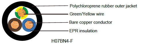
H07BN4-F WIND90
Application and Description
H07BN4-F WIND90 cables are made with synthetic rubbers having an excellent temperature resistance and can be
used either in dry, humid or wet places or in contact with oil or grease, in weather conditions and under
medium mechanical stress, for example power supply to equipment in industrial plants, large size boilers,
heating plates, portable lamps, electrical tools such as drilling machines, disk saws, portable engines and
machines, building and farming equipments etc. These cables are also suitable for stationary equipments,
for example designed for wind-tower application, the particular conductor Cable Construction and the used
materials have improved the cable torsion resistance (max 150°/m), key requirement for drop cables in windgenerators,on plaster in temporary buildings and builders huts, and wiring in machinery elevators or similar.
Suitable for caravans and camping equipment. Especially recommended for service temperature up to 90º
C together with good resistance to hot grease and oil. Therefore these cables are ideal for use in plants and
industries dealing with grease, oil or oil emulsion treatments, transformation or handling.
Standard and Approval
<HAR> VDE-0282 Part-12,CENELEC HD 22.12 S1, CEI 20-19 p.12, CEI 20-35 (EN 60332-1), IEMMEQU
HAR IEC 60245-4, IEC 60754-1/2, ROHS compliant
Cable Construction
Fine bare copper strands
Strands to VDE-0295 Class-5, IEC 60228 Class-5
EPR(Ethylene Propylene Rubber) rubber EI7 insulation
Color code VDE-0293-308
Special polychloroprene rubber outer jacket EM7
Technical Characteristics
Working voltage: 450/750 volts
Test voltage: 2500 volts
Flexing bending radius: 6.0 x Ø
Fixed bending radius: 4.0 x Ø
Temperature Range: -40º C to +90º C
Wind energy: -15º C to +90º C
Maximum Short Circuit Temperature: +250º C
Flame retardant: IEC 60332.1C2/NF C 32-070
Insulation resistance: 20 MΩ x km
Cable Parameter
AWG |
No. of Cores x Nominal Cross Sectional Area # x mm² |
Nominal Thickness of Insulation mm |
Nominal Thickness of Sheath mm |
Nominal Overall Diameter mm |
Nominal Copper Weight kg/Km |
Nominal Weight kg/Km |
17(32/32) |
2 x 1 |
0.8 |
1.3 |
8.2 |
19 |
93 |
17(32/32) |
3 x 1 |
0.8 |
1.4 |
8.9 |
29 |
114 |
17(32/32) |
4 x 1 |
0.8 |
1.5 |
9.8 |
38 |
139 |
16(30/30) |
1 x 1.5 |
0.8 |
1.4 |
5.9 |
14.4 |
50 |
16(30/30) |
2 x 1.5 |
0.8 |
1.5 |
9.3 |
29 |
118 |
16(30/30) |
3 x 1.5 |
0.8 |
1.6 |
10.0 |
43 |
144 |
16(30/30) |
4 x 1.5 |
0.8 |
1.7 |
11.0 |
58 |
177 |
16(30/30) |
5 x 1.5 |
0.8 |
1.8 |
12.1 |
72 |
226 |
16(30/30) |
7 x 1.5 |
0.8 |
2.6 |
14.7 |
101 |
385 |
16(30/30) |
12 x 1.5 |
0.8 |
2.9 |
18.8 |
173 |
516 |
16(30/30) |
19 x 1.5 |
0.8 |
3.2 |
22.0 |
274 |
800 |
16(30/30) |
24 x 1.5 |
0.8 |
3.5 |
25.7 |
346 |
882 |
14(50/30) |
1 x 2.5 |
0.9 |
1.4 |
6.5 |
24 |
65 |
14(50/30) |
2 x 2.5 |
0.9 |
1.7 |
10.9 |
48 |
172 |
14(50/30) |
3 x 2.5 |
0.9 |
1.8 |
11.7 |
72 |
210 |
14(50/30) |
4 x 2.5 |
0.9 |
1.9 |
12.8 |
96 |
257 |
14(50/30) |
5 x 2.5 |
0.9 |
2.0 |
14.1 |
120 |
329 |
14(50/30) |
7 x 2.5 |
0.9 |
2.8 |
17.1 |
168 |
445 |
14(50/30) |
12 x 2.5 |
0.9 |
3.1 |
22.1 |
288 |
702 |
14(50/30) |
19 x 2.5 |
0.9 |
3.5 |
26.0 |
456 |
1030 |
14(50/30) |
24 x 2.5 |
0.9 |
3.9 |
30.4 |
576 |
1312 |
12(56/28) |
1 x 4 |
1.0 |
1.5 |
7.4 |
38 |
89 |
12(56/28) |
2 x 4 |
1.0 |
1.8 |
12.6 |
77 |
238 |
12(56/28) |
3 x 4 |
1.0 |
1.9 |
13.5 |
115 |
292 |
12(56/28) |
4 x 4 |
1.0 |
2.0 |
14.8 |
154 |
359 |
12(56/28) |
5 x 4 |
1.0 |
2.2 |
16.3 |
192 |
422 |
12(56/28) |
7 x 4 |
1.0 |
3.1 |
19.6 |
269 |
618 |
10(84/28) |
1 x 6 |
1.0 |
1.6 |
8.1 |
58 |
115 |
10(84/28) |
2 x 6 |
1.0 |
1.8 |
13.8 |
173 |
282 |
10(84/28) |
3 x 6 |
1.0 |
2.1 |
14.8 |
173 |
355 |
10(84/28) |
4 x 6 |
1.0 |
2.3 |
16.4 |
230 |
449 |
10(84/28) |
5 x 6 |
1.2 |
3.6 |
18.1 |
288 |
567 |
8(80/26) |
1 x 10 |
1.2 |
1.8 |
10.4 |
96 |
190 |
8(80/26) |
2 x 10 |
1.2 |
2.3 |
19.4 |
288 |
539 |
8(80/26) |
3 x 10 |
1.2 |
3.3 |
20.7 |
288 |
674 |
8(80/26) |
4 x 10 |
1.2 |
3.4 |
22.6 |
384 |
833 |
8(80/26) |
5 x 10 |
1.2 |
3.6 |
24.8 |
480 |
1010 |
6(128/26) |
1 x 16 |
1.2 |
1.9 |
11.6 |
154 |
259 |
6(128/26) |
2 x 16 |
1.2 |
2.8 |
21.8 |
461 |
722 |
6(128/26) |
3 x 16 |
1.2 |
3.5 |
23.3 |
461 |
913 |
6(128/26) |
4 x 16 |
1.2 |
3.6 |
25.4 |
614 |
1138 |
6(128/26) |
5 x 16 |
1.2 |
3.9 |
28.1 |
768 |
1400 |
4(200/26) |
1 x25 |
1.4 |
2 |
13.7 |
240 |
375 |
4(200/26) |
2 x 25 |
1.4 |
3.3 |
25.9 |
960 |
1043 |
4(200/26) |
4 x 25 |
1.4 |
4.1 |
30.8 |
960 |
1714 |
4(200/26) |
5 x 25 |
1.4 |
4.4 |
33.9 |
1200 |
2096 |
2(280/26) |
1 x 35 |
1.4 |
2.2 |
15.4 |
336 |
492 |
2(280/26) |
3 x 35 |
1.4 |
4.1 |
31.0 |
1008 |
1745 |
2(280/26) |
4 x 35 |
1.4 |
4.4 |
34.3 |
1344 |
2204 |
2(280/26) |
5 x 35 |
1.4 |
4.7 |
39.6 |
1680 |
2810 |
1(400/26) |
1 x 50 |
1.6 |
2.4 |
17.7 |
480 |
675 |
1(400/26) |
3 x 50 |
1.6 |
3.6 |
35.8 |
1920 |
2409 |
1(400/26) |
4 x 50 |
1.6 |
4.8 |
39.6 |
1920 |
3029 |
1(400/26) |
5 x 50 |
1.6 |
5.1 |
44.1 |
2400 |
4050 |
2/0(356/24) |
1 x 70 |
1.6 |
2.6 |
20.0 |
672 |
908 |
2/0(356/24) |
3 x 70 |
1.6 |
4.2 |
40.5 |
2688 |
3211 |
2/0(356/24) |
4 x 70 |
1.6 |
5.2 |
44.9 |
2688 |
4121 |
3/0(485/24) |
1 x 95 |
1.8 |
2.8 |
22.1 |
912 |
1171 |
3/0(485/24) |
3 x 95 |
1.8 |
4.8 |
45.1 |
3648 |
4210 |
3/0(485/24) |
4 x 95 |
1.8 |
5.9 |
50.4 |
3648 |
5361 |
4/0(614/24) |
1x 120 |
1.8 |
3 |
24.5 |
1152 |
1445 |
4/0(614/24) |
3 x 120 |
1.8 |
4.8 |
49.9 |
4608 |
5205 |
4/0(614/24) |
4 x 120 |
1.8 |
6 |
55.3 |
4608 |
6546 |
300 MCM (765/24) |
1 x 150 |
2 |
3.2 |
26.9 |
1440 |
1783 |
300 MCM (765/24) |
3 x 150 |
2 |
5.2 |
54.8 |
5760 |
6389 |
300 MCM (765/24) |
4 x 150 |
2 |
6.4 |
60.9 |
5760 |
8095 |
350 MCM (944/24) |
1 x 185 |
2.2 |
3.4 |
28.9 |
1776 |
2125 |
350 MCM (944/24) |
4 x 185 |
2.2 |
6.8 |
65.7 |
7104 |
9652 |
500 MCM (1221/24) |
1x 240 |
2.4 |
3.5 |
32.6 |
23.4 |
2733 |
4x 240 |
2.4 |
7.2 |
75.5 |
9216 |
12614 |
|
1 x 300 |
2.6 |
3.6 |
36.5 |
2880 |
3348 |
|
1 x 400 |
2.8 |
3.8 |
39.9 |
4327 |
||
1x 500 |
3 |
4 |
45.8 |
5450 |