| Telephone Cables | ||||||||||||
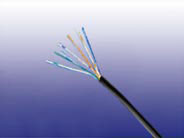
![]() Indoor Central Office Cables to CW 1308
Indoor Central Office Cables to CW 1308
Application
The cables are designed to handle low frequency signals for short range applications, suitable for internal connection of telephone systems and other communications equipment. Also, they are designed to be terminated in insulation displacement connectors (IDC).Insulated and sheathed in PVC or LSZH, these cables offer an extremely cost effective general signal cable for fixed installation.
Standards
• CW 1308
Construction
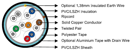
Conductors
Solid annealed copper sized 0.4/0.5mm as per class 1 of BS 6360/IEC 60228
Insulation
Colour coded PVC TI 54/LSZH for copper conductor & PVC TI 54/LSZH for the 1.38mm earth conductor
Twisted Pairs
Insulated conductors are twisted into pairs with varying lay length to minimize crosstalk
Cabling Element
Pairs or triples
Cable Core Assembly
There are two modes of construction: layer construction and unit construction. For layer construction, cables are laid up in concentric layers to form a compact and circular cable. Layer construction is for general use, including two cables for installation in customer’s premises where a good appearance is required. For Unit construction, the elements shall be pairs and laid up as units or sub-units. This include unit of 20 pairs which contain an insulated earth conductor of 1.38mm, for use with customer distribution schemes; unit of 16 pairs for use with the binary number system and unit of 30 pairs for use with Pulse Code Modulation (PCM) systems.
Core Wrapping
Cable containing more than 6 pairs have a polyester tape applied over the cable core prior to sheathing
Screen (optional)
A 24μ aluminium polyester foil shield can be provided for fully enclosing the core with an overlap
Sheath
PVC TM51 grade or LSZH compound. Grey, White, Cream or Black colours are standard
Ripcord
Nylon ripcord may be placed parallel to the cores to facilitate sheath removal
Drain Wire (optional)
For screened cables, a solid tinned 0.5mm copper drain wire may be longitudinally laid to ensure electrical continuity of the screen
Electrical & Mechanical Properties
Nominal Conductor Diameter |
mm |
0.4 |
0.5 |
1.38 |
Conductor Size |
mm2 |
0.126 |
0.196 |
1.495 |
Ω/km |
153 |
97.8 |
12.4 |
|
MΩ.km |
50 |
50 |
N/A |
|
| Maximum Capacitance Unbalance @0.8KHz-3.0KHz pair-to-pair | pF/500m | 200(Unit)/300(Layer) | 500 | N/A |
Minimum Insulation Thickness |
mm |
0.15 | 0.15 | 0.55 |
Maximum Insulated Conductor Diameter |
mm |
0.85 | 0.95 | 3.5 |
Mechanical and Thermal Properties
Temperature range during operation (fixed state): -30°C – +70°C
Temperature range during installation (mobile state): -20°C – +50°C
Minimum bending radius: 7.5 x Overall Diameter
Color Code
Make Up & Unit Identification Colours – 16 Pair Unit
| Pair Size | 8 Pairs | 16 Pairs | 32 Pairs | 64 Pairs | 128 Pairs | 256 Pairs |
| Number of Units | ||||||
| Centre 1st Layer 2nd Layer |
½ | 1 | 4 X ½ | 1 | 4 X ½ | 1 |
| 6 X ½ | 6 | 5 | ||||
| 10 | ||||||
| Unit No. | Colours of Unit Lappings | |||||
| 1 | ORANGE | ORANGE | ORANGE | ORANGE | ORANGE | ORANGE |
2 |
GREEN |
ORANGE |
GREEN |
ORANGE |
||
3 |
|
NATURAL |
ORANGE |
NATURAL |
||
4 |
|
GREEN |
NATURAL |
NATURAL |
||
5 |
|
|
NATURAL |
NATURAL |
||
6 |
|
|
NATURAL |
GREEN |
||
7 |
|
|
NATURAL |
ORANGE |
||
7 |
|
|
GREEN |
NATURAL |
||
9-15 |
|
|
|
NATURAL |
||
16 |
|
|
|
GREEN |
||
Note: ½ refers to sub-units of 8 Pairs.
Make Up & Unit Identification Colours – 20 Pair Unit
| Pair Size | 10 Pairs | 20 Pairs | 40 Pairs | 50 Pairs | 80 Pairs | 100 Pairs | 160 Pairs | 320 Pairs |
| Number of Units | ||||||||
| Centre 1st Layer 2nd Layer |
½ | 1 | 4 X ½ | 5 X ½ | 1 | 1 | 4 X ½ | 1 |
| 6 X ½ | 8 X ½ | 6 | 5 | |||||
| ** | 10 | |||||||
| Unit No. | Colours of Unit Lappings | |||||||
1 |
ORANGE |
ORANGE |
ORANGE |
ORANGE |
ORANGE |
ORANGE |
ORANGE |
ORANGE |
2 |
|
|
GREEN |
NATURAL |
ORANGE |
ORANGE |
GREEN |
ORANGE |
3 |
|
|
|
GREEN* |
NATURAL |
NATURAL |
ORANGE |
NATURAL |
4 |
|
|
|
|
GREEN |
NATURAL |
NATURAL |
NATURAL |
5 |
|
|
|
|
|
GREEN |
NATURAL |
NATURAL |
6 |
|
|
|
|
|
|
NATURAL |
GREEN |
7 |
|
|
|
|
|
|
NATURAL |
ORANGE |
7 |
|
|
|
|
|
|
GREEN |
NATURAL |
9-15 |
|
|
|
|
|
|
|
NATURAL |
16 |
|
|
|
|
|
|
|
GREEN |
Note 1: ½ refers to sub-units of 10 Pairs.
Note 2: These cables include the single 1.38mm diameter insulated conductor.
* The Green colour lapping shall be applied to the last ½ unit.
** At the manufacturer’s discretion the first layer may be 4 x 1.
Alternatively the centre layer may be 5 x 1 in which case the unit lappings shall be coloured Orange,3 x 1 Natural, Green.
Make Up & Unit Identification Colours – 30 Pair Unit
| Pair Size | 30 Pairs | 120 Pairs | 150 Pairs |
| Number of Units | |||
| Centre 1st Layer |
1 | 1 | 1 |
| 6 X ½ | 8 X ½ | ||
| Unit No. | Colours of Unit Lappings | ||
1 |
ORANGE |
ORANGE |
ORANGE |
2 |
|
ORANGE |
ORANGE |
3 |
|
NATURAL |
NATURAL |
4 |
|
GREEN |
BLUE |
5 |
|
|
GREEN |
Note 1: ½ refers to sub-units of 15 Pairs.
Colour Scheme for Pairs & Triples
| Cabling Element No. |
a-wire | b-wire | Cabling Element No. |
a-wire | b-wire | Cabling Element No. |
a-wire | b-wire | ||||||
| 1 | WHITE | Blue | BLUE | White | 11 | BLACK | Blue | BLUE | Black | 21 | VIOLET | Blue | BLUE | Violet |
| 2 | WHITE | Orange | ORANGE | White | 12 | BLACK | Orange | ORANGE | Black | 22 | VIOLET | Orange | ORANGE | Violet |
| 3 | WHITE | Green |
GREEN |
White | 13 | BLACK | Green | GREEN | Black | 23 | VIOLET | Green | GREEN | Violet |
| 4 | WHITE | Brown |
BROWN |
White | 14 | BLACK | Brown | BROWN | Black | 24 | VIOLET | Brown | BROWN | Violet |
| 5 | WHITE | Grey |
GREY |
White | 15 | BLACK | Grey | GREY | Black | 25 | VIOLET | Grey | GREY | Violet |
| 6 | RED | Blue | BLUE | Red | 16 | YELLOW | Blue | BLUE | Yellow | 26 | PINK | Blue | BLUE | Pink |
| 7 | RED | Orange | ORANGE | Red | 17 | YELLOW | Orange | ORANGE | Yellow | 27 | PINK | Orange | ORANGE | Pink |
8 |
RED |
Green |
GREEN |
Red |
18 |
YELLOW |
Green | GREEN | Yellow |
28 |
PINK |
Green |
GREEN |
Pink |
9 |
RED |
Brown |
BROWN |
Red |
19 |
YELLOW |
Brown | BROWN | Yellow |
29 |
PINK |
Brown |
BROWN |
Pink |
10 |
RED |
Grey |
GREY |
Red |
20 |
YELLOW |
Grey | GREY | Yellow |
30 |
PINK |
Grey |
GREY |
Pink |
In each triple, the c-wire shall be coloured TURQUOISE
Dimensions And Weight
Cable Code |
Number |
Minimum Insulation |
Make Up |
Minimum Sheath |
Maximum Overall |
Nominal |
| 0.4mm Conductor, 0.85mm Insulated Wire-Layer (Pair) | ||||||
TP1308-YY-2P04 |
2 |
0.15 |
Layer |
0.4 |
3.9 |
15 |
TP1308-YY-3P04 |
3 |
0.15 |
Layer |
0.5 |
5.3 |
21 |
TP1308-YY-4P04 |
4 |
0.15 |
Layer |
0.5 |
5.8 |
25 |
TP1308-YY-6P04 |
6 |
0.15 |
Layer |
0.6 |
6.8 |
37 |
TP1308-YY-10P04 |
10 |
0.15 |
Layer |
0.6 |
8.3 |
54 |
TP1308-YY-12P04 |
12 |
0.15 |
Layer |
0.7 |
8.9 |
61 |
TP1308-YY-20P04 |
20 |
0.15 |
Layer |
0.7 |
10.4 |
95 |
TP1308-YY-25P04 |
25 |
0.15 |
Layer |
0.8 |
11.1 |
115 |
| 0.5mm Conductor, 0.95mm Insulated Wire-Layer (Pair) | ||||||
TP1308-YY-3P05 |
3 |
0.15 |
Layer |
0.65 |
5.0 |
25 |
TP1308-YY-4P05 |
4 |
0.15 |
Layer |
0.65 |
5.8 |
30 |
TP1308-YY-6P05 |
6 |
0.15 |
Layer |
0.6 |
6.8 |
40 |
TP1308-YY-10P05 |
10 |
0.15 |
Layer |
0.6 |
8.3 |
50 |
TP1308-YY-12P05 |
12 |
0.15 |
Layer |
0.7 |
9.1 |
75 |
TP1308-YY-15P05 |
15 |
0.15 |
Layer |
0.7 |
9.8 |
98 |
TP1308-YY-20P05 |
20* |
0.15 |
Layer |
0.8 |
10.7 |
140 |
TP1308-YY-25P05 |
25 |
0.15 |
Layer |
0.8 |
11.4 |
184 |
*This cable has an additional 0.5mm insulated conductor coloured VIOLET.
| Cable Code | Number of Triples |
Minimum Insulation Thickness mm |
Minimum Primary Sheath Thickness mm |
Minimum Secondary Sheath Thickness mm |
Maximum Overall Diameter mm |
Nominal Weight kg/km |
| 0.4mm Conductor, 0.85mm Insulated Wire-Layer (Triple) | ||||||
TP1308-YY-1T04 |
1 |
0.15 |
0.4 |
— |
3.8 |
17 |
TP1308-YY-5T04 |
5 |
0.15 |
0.4 |
0.8 |
13.0 |
45 |
| 0.5mm Conductor, 0.95mm Insulated Wire-Layer (Triple) | ||||||
TP1308-YY-1T05 |
1 |
0.15 |
0.4 |
— |
4.0 |
20 |
TP1308-YY-5T05 |
5 |
0.15 |
0.4 |
0.8 |
13.5 |
65 |
| Cable Code | Number of Pairs |
Minimum Insulation Thickness mm |
Size of Unit | Minimum Sheath Thickness mm |
Maximum Overall Diameter mm |
Nominal Weight kg/km |
| 0.4mm Conductor, 0.85mm Insulated Wire-Unit (Pair) | ||||||
TP1308-YY-8P04 |
8 |
0.15 |
1/2*16 |
0.6 |
7.2 |
45 |
TP1308-YY-16P04 |
16 |
0.15 |
16 |
0.7 |
9.8 |
80 |
TP1308-YY-32P04 |
32 |
0.15 |
16 |
0.8 |
12.0 |
145 |
TP1308-YY-64P04 |
64 |
0.15 |
16 |
1.1 |
16.0 |
260 |
TP1308-YY-30P04 |
30 |
0.15 |
30 |
0.8 |
11.8 |
130 |
TP1308-YY-120P04 |
120 |
0.15 |
30 |
1.6 |
24.8 |
480 |
TP1308-YY-150P04 |
150 |
0.15 |
30 |
1.7 |
26.0 |
590 |
| 0.5mm Conductor, 0.95mm Insulated Wire-Unit (Pair) | ||||||
TP1308-YY-8P05 |
8 |
0.15 |
1/2*16 |
0.6 |
7.6 |
65 |
TP1308-YY-16P05 |
16 |
0.15 |
16 |
0.7 |
10.2 |
115 |
TP1308-YY-32P05 |
32 |
0.15 |
16 |
0.8 |
12.4 |
205 |
TP1308-YY-64P05 |
64 |
0.15 |
16 |
1.1 |
16.5 |
390 |
TP1308-YY-128P05 |
128 |
0.15 |
16 |
1.6 |
25.4 |
785 |
TP1308-YY-256P05 |
256 |
0.15 |
16 |
2.0 |
35.2 |
1460 |
TP1308-YY-(10P+E)05 |
10+E |
0.15 |
1/2*20 |
0.6 |
8.6 |
85 |
TP1308-YY-(20P+E)05 |
20+E |
0.15 |
20 |
0.7 |
12.0 |
160 |
TP1308-YY-(40P+E)05 |
40+E |
0.15 |
20 |
0.9 |
15.0 |
371 |
TP1308-YY-(50P+E)05 |
50+E |
0.15 |
20 |
1.0 |
17.0 |
427 |
TP1308-YY-(80P+E)05 |
80+E |
0.15 |
20 |
1.2 |
22.5 |
610 |
TP1308-YY-(100P+E)05 |
100+E |
0.15 |
20 |
1.5 |
27.0 |
630 |
TP1308-YY-(160P+E)05 |
160+E |
0.15 |
20 |
1.7 |
30.3 |
1059 |
TP1308-YY-(320P+E)05 |
320+E |
0.15 |
20 |
2.2 |
39.5 |
2255 |
TP1308-YY-30P05 |
30 |
0.15 |
30 |
0.8 |
12.2 |
190 |
TP1308-YY-120P05 |
120 |
0.15 |
30 |
1.6 |
25.1 |
765 |
TP1308-YY-150P05 |
150 |
0.15 |
30 |
1.7 |
26.0 |
1100 |
Note: For those cables with BT designation suffixed E contain a 1.38mm diameter insulated earth conductor