| EN50288-7 Cables | |||
| BS5308 Cable | ESI Cable | BS 6231 Cable | DEF Standard Cable | EN50288-7 LSZH Cables | EN50288-7 PVC Cables | NF M 87-202 |
Pe Insulated, PVc sheathed & overall screened Instrumentation cables (Multipair)
re-2Y(st)Y 90°c / 300V
APPLICATION
EN 50228-7 cables are used for transmission of analogue and digital signals in instrument and control systems; allowed for use
in zone 1 and zone 2, group II, classified areas (IEC 79-14), not allowed for direct connection to low
impedance sources, e.g. public mains electricity supply.
Recommended for indoor and outdoor installation, on racks, trays, in conduits, in dry and wet
locations; not for direct burial.
Recommended for use as fire protection measure for people and important material assets.
STANDARDS
Basic design to EN 50288-7
FIRE PERFORMANCE
| Flame Retardance (Single Vertical Wire Test) | EN 60332-1-2; IEC 60332-1-2; BS EN 60332-1-2; VDE 0482-332-1; NBN C 30-004 (cat. F1); NF C32-070-2.1(C2); CEI 20-35/1-2; EN 50265-2-1*; DIN VDE 0482-265-2-1* |
| Reduced Fire Propagation (Vertically-mounted bundled wires & cable test) | EN 60332-3-24 (cat. C); IEC 60332-3-24; BS EN 60332-3-24; VDE 0482-332-3; NBN C 30-004 (cat. F2); NF C32-070-2.2(C1); CEI 20-22/3-4; EN 50266-2-4*; DIN VDE 0482-266-2-4 |
| Halogen Free | IEC 60754-1; EN 50267-2-1; DIN VDE 0482-267-2-1; CEI 20-37/2-1 ; BS 6425-1* |
| No Corrosive Gas Emission | IEC 60754-2; EN 50267-2-2; DIN VDE 0482-267-2-2; CEI 20-37/2-2 ; BS 6425-2* |
| Minimum Smoke Emission | IEC 61034-1&2; EN 61034 -1&2; DIN VDE 0482-1034-1&2; CEI 20-37/3-1&2; EN 50268-1&2*; BS 7622-1&2* |
| No Toxic gases | NES 02-713; NF C 20-454 |
Note: Asterisk * denotes superseded standard, *** denotes optional.
VOLTAGE RATING
300V
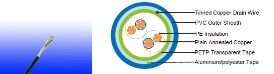
CABLE CONSTRUCTION
uctor: Annealed copper solid or plain copper stranded to IEC 60228 Class 2.
Insulation: PE compound as per EN 50290. 2-23.
Pairs: Two insulated conductors uniformly twisted together with a lay not exceeding 100mm
Binder tape: PETP transparent tape
Overall Screen: Aluminium/polyester tape is applied over the laid up pairs metallic side down in
contact with tinned copper drain wire, 0.5mm²
Outer Sheath: Thermoplastic PVC compound as per EN 50290-2-22. UV resistance, hydrocarbon
resistance, oil resistance, anti rodent and anti termite properties can be offered as option.
Compliance to fire performance standard (IEC 60332-1, IEC 60332-3, UL 1581, UL 1666 etc)
depends on the oxygen index
COLOUR CODE
Insulation: Black / White, continuously numbered on white core(1, 2..)for multipair.
Outer Sheath: Black or blue for intrinsically safe systems
PHYSICAL AND THERMAL PROPERTIES
Temperature Range During Operation (Fixed State): -30°C – +90°C
Temperature Range During Installation (Mobile State): -5°C – +50°C
Minimum Bending Radius: 7.5 X Overall Diameter
Sunlight Resistance: UL 1581 section 1200
Oil Resistance: ICEA S-73-532(Test temperature +60°C, duration 4h. Retention: min 60% of tensile
strength/min.60% of elongation)
ELECTRICAL PROPERTIES
Conductor Area Size |
mm 2 |
0.5 |
0.75 |
1.0 |
1.3 |
1.5 |
||
Insulation thickness (nominal) |
mm |
0.35 |
0.38 |
0.4 |
0.45 |
0.45 |
||
Conductor resistance (20°C) |
Ω/km |
36.7 |
25 |
18.5 |
14.2 |
12.3 |
||
Insulation resistance (20°C) |
MΩ.km(Min.) |
5000 |
||||||
Mutual Capacitance (1 kHz) |
pF/m(Max.) |
|
||||||
|
≤ 4 pairs |
90 |
90 |
90 |
102 |
102 |
||
|
|
|||||||
|
all other pairs |
75 |
75 |
75 |
85 |
85 |
||
|
|
|||||||
Capacitance unbalance(1 kHz) |
pF/500 m (Max.) |
500 |
||||||
Inductance |
mH/km (Max.) |
1 |
|||||
L / R (ratio) (max.) |
μH/Ω |
25 |
25 |
25 |
40 |
40 |
|
Operating voltage Urms |
V |
300 |
|||||
Test Voltage |
Core to Core |
V |
1500 |
||||
Core to Screen |
V |
1500 |
|||||
CONSTRUCTION PARAMETERS
Caledonian Cable Code |
RE-2Y(St)Y |
||||
No. of Pairsx2 xCross Section |
Nominal Insulation Thickness |
Nominal Outer Sheath Thickness |
Nominal Overall Diameter |
Approx. Weight |
|
|
No.x2xmm2 |
mm |
mm |
mm |
kg/km |
0.5mm2, Multipair |
|||||
RE-2Y(St)Y 2P0.5 |
2x2x0.5 |
0.35 |
0.9 |
7.6 |
66 |
RE-2Y(St)Y 4P0.5 |
4x2x0.5 |
0.35 |
0.9 |
8.8 |
98 |
RE-2Y(St)Y 5P0.5 |
5x2x0.5 |
0.35 |
1.0 |
9.8 |
118 |
RE-2Y(St)Y 6P0.5 |
6x2x0.5 |
0.35 |
1.0 |
10.6 |
138 |
RE-2Y(St)Y 8P0.5 |
8x2x0.5 |
0.35 |
1.0 |
11.3 |
160 |
RE-2Y(St)Y 10P0.5 |
10x2x0.5 |
0.35 |
1.1 |
12.9 |
201 |
RE-2Y(St)Y 12P0.5 |
12x2x0.5 |
0.35 |
1.1 |
13.5 |
236 |
RE-2Y(St)Y 16P0.5 |
16x2x0.5 |
0.35 |
1.1 |
15.2 |
300 |
RE-2Y(St)Y 20P0.5 |
20x2x0.5 |
0.35 |
1.2 |
16.9 |
367 |
RE-2Y(St)Y 24P0.5 |
24x2x0.5 |
0.35 |
1.2 |
18.3 |
419 |
0.75mm2, Multipair |
|||||
RE-2Y(St)Y 2P0.75 |
2x2x0.75 |
0.38 |
0.9 |
8.5 |
87 |
RE-2Y(St)Y 4P0.75 |
3x2x0.75 |
0.38 |
1.0 |
10.0 |
123 |
RE-2Y(St)Y 5P0.75 |
4x2x0.75 |
0.38 |
1.0 |
10.9 |
150 |
RE-2Y(St)Y 6P0.75 |
5x2x0.75 |
0.38 |
1.0 |
11.8 |
175 |
RE-2Y(St)Y 8P0.75 |
8x2x0.75 |
0.38 |
1.1 |
12.8 |
220 |
RE-2Y(St)Y 10P0.75 |
10x2x0.75 |
0.38 |
1.1 |
14.5 |
267 |
RE-2Y(St)Y 12P0.75 |
12x2x0.75 |
0.38 |
1.1 |
15.1 |
298 |
RE-2Y(St)Y 16P0.75 |
16x2x0.75 |
0.38 |
1.2 |
17.3 |
409 |
| Caledonian Cable Code | RE-2Y(St)Y | ||||
| No. of Pairsx2 xCross Section | Nominal Insulation Thickness | Nominal Outer Sheath Thickness | Nominal Overall Diameter | Approx. Weight | |
| No.x2xmm2 | mm | mm | mm | kg/km | |
| RE-2Y(St)Y 20P0.75 | 20x2x0.75 | 0.38 | 1.3 | 19.2 | 480 |
| RE-2Y(St)Y 24P0.75 | 24x2x0.75 | 0.38 | 1.3 | 20.8 | 561 |
| 1.0mm2, Multipair | |||||
| RE-2Y(St)Y 2P1.0 | 2x2x1.0 | 0.4 | 0.9 | 9.2 | 102 |
| RE-2Y(St)Y 4P1.0 | 3x2x1.0 | 0.4 | 1.0 | 10.9 | 156 |
| RE-2Y(St)Y 5P1.0 | 4x2x1.0 | 0.4 | 1.0 | 11.9 | 183 |
| RE-2Y(St)Y 6P1.0 | 5x2x1.0 | 0.4 | 1.0 | 13.0 | 224 |
| RE-2Y(St)Y 8P1.0 | 8x2x1.0 | 0.4 | 1.1 | 14.0 | 273 |
| RE-2Y(St)Y 10P1.0 | 10x2x1.0 | 0.4 | 1.1 | 15.9 | 324 |
| RE-2Y(St)Y 12P1.0 | 12x2x1.0 | 0.4 | 1.2 | 16.8 | 383 |
| RE-2Y(St)Y 16P1.0 | 16x2x1.0 | 0.4 | 1.2 | 19.0 | 513 |
| RE-2Y(St)Y 20P1.0 | 20x2x1.0 | 0.4 | 1.3 | 21.1 | 619 |
| RE-2Y(St)Y 24P1.0 | 24x2x1.0 | 0.4 | 1.4 | 23.1 | 738 |
| 1.3mm2, Multipair | |||||
| RE-2Y(St)Y 2P1.3 | 2x2x1.3 | 0.45 | 1.0 | 10.4 | 122 |
| RE-2Y(St)Y 4P1.3 | 3x2x1.3 | 0.45 | 1.0 | 12.0 | 190 |
| RE-2Y(St)Y 5P1.3 | 4x2x1.3 | 0.45 | 1.1 | 13.4 | 233 |
| RE-2Y(St)Y 6P1.3 | 5x2x1.3 | 0.45 | 1.1 | 14.6 | 273 |
| RE-2Y(St)Y 8P1.3 | 8x2x1.3 | 0.45 | 1.2 | 15.7 | 330 |
| RE-2Y(St)Y 10P1.3 | 10x2x1.3 | 0.45 | 1.2 | 17.9 | 422 |
| RE-2Y(St)Y 12P1.3 | 12x2x1.3 | 0.45 | 1.3 | 18.9 | 487 |
| RE-2Y(St)Y 16P1.3 | 16x2x1.3 | 0.45 | 1.3 | 21.4 | 678 |
| RE-2Y(St)Y 20P1.3 | 20x2x1.3 | 0.45 | 1.4 | 23.8 | 790 |
| RE-2Y(St)Y 24P1.3 | 24x2x1.3 | 0.45 | 1.5 | 25.9 | 921 |
| 1.5mm2, Multipair | |||||
| RE-2Y(St)Y 2P1.5 | 2x2x1.5 | 0.45 | 1.0 | 10.8 | 139 |
| RE-2Y(St)Y 4P1.5 | 3x2x1.5 | 0.45 | 1.1 | 12.7 | 212 |
| Caledonian Cable Code | RE-2Y(St)Y | ||||
| No. of Pairsx2 xCross Section | Nominal Insulation Thickness | Nominal Outer Sheath Thickness | Nominal Overall Diameter | Approx. Weight | |
| No.x2xmm2 | mm | mm | mm | kg/km | |
| RE-2Y(St)Y 5P1.5 | 4x2x1.5 | 0.45 | 1.1 | 14.0 | 259 |
| RE-2Y(St)Y 6P1.5 | 5x2x1.5 | 0.45 | 1.2 | 15.2 | 312 |
| RE-2Y(St)Y 8P1.5 | 8x2x1.5 | 0.45 | 1.2 | 16.4 | 378 |
| RE-2Y(St)Y 10P1.5 | 10x2x1.5 | 0.45 | 1.3 | 18.8 | 473 |
| RE-2Y(St)Y 12P1.5 | 12x2x1.5 | 0.45 | 1.3 | 19.7 | 548 |
| RE-2Y(St)Y 16P1.5 | 16x2x1.5 | 0.45 | 1.4 | 22.5 | 727 |
| RE-2Y(St)Y 20P1.5 | 20x2x1.5 | 0.45 | 1.5 | 25.0 | 903 |
| RE-2Y(St)Y 24P1.5 | 24x2x1.5 | 0.45 | 1.5 | 27.1 | 1051 |
Note : Other conductor sizes & core configurations are available upon request.