CALEDONIAN
Professional Cable Provider
 English
Quick Contact


LV Cables
7.24 PVC, PVC/SWA/PVC, PVC/PVC CABLES
Single core PVC, PVC/PVC cables shall comply with SS358, IEC 60227, IEC 60228, IEC 60228A, IEC 60811 and IEC 60885 with voltage grade of 450/750V.
Multi core cables shall comply with BS6346 with voltage grade of 600/1000V.
High conductivity copper conductors shall comply with IEC 60228, in respect of dimension and resistances. Where shaped conductors are used, they shall be compacted to reduce dimensions and to give a smoother profile. Sizes shall be designated by the nominal cross-sectional area.
Where necessary, PVC fillers shall be used between laid-up wires. In the case of cables with extruded bedding, the cores shall be bound with a non-hygroscopic tape before the bedding is extruded.
For twin and multi-core cables the bedding shall consist of two or more layers of PVC tape. For cables with circular conductors, the bedding shall be an extruded layer of PVC.
For armoured cables, the armour shall consist of a single layer of galvanised steel wire or tape as specified. Armouring for single core cables shall consist of non- magnetic material.
The cable shall be finished in an extruded black or grey PVC oversheath, the thickness of which shall comply with SS358, IEC 60227 as appropriate. The external surface of the oversheath shall be embossed with the voltage designation and the manufacturer's name.
Corrosion resistant outdoor type cable glands of the appropriate size shall be used where cables enter or exit from a switchboard/DB and/or where required. Glands shall comply with BS 6121 with integral earth facility. The termination of armoured cable shall be in accordance to manufacturer's recommendation and/or to the M&E Engineer's approval.
The sizing of the cable gland shall be based on the nominal dimension of the cable.
Proper compression cable lugs shall be used for terminating the cable cores onto terminals of devices and equipment.
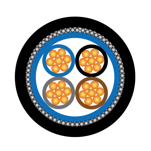
The cores of the cables shall be identified as follows:
Three Core (three phase) - Brown, Black, Grey
Four Core (three phase) - Brown, Black, Grey, Blue
Auxilliary cable shall be white with black numbers printed on the cores, commencing 1, 2, 3, 4 upwards.
7.25 CROSS-LINKED POLYETHYLENE (XLPE) CABLES
Cross-linked polyethylene (XLPE) cables shall be of 600/1000V grade and shall be stranded copper conductor, cross-linked polyethylene insulated, PVC inner sheathed with galvanized steel-wire armour (as required) and PVC over sheathed power cables. All cables shall comply with IEC 60228, IEC 60228A, IEC 60811 and IEC 60885.
The current carrying capacity and the short circuit final temperature of the cable shall comply with IEC 60287 and IEC 60724 respectively.
Conductors shall be Class 2 annealed compacted stranded plain copper. Insulation shall be cross-linked polyethylene (XLPE) with a high degree of cross linking, free from contaminants and air voids, good heat resistance and it shall be applied by an extrusion process. The XLPE insulation shall be suitable for use in wet and dry locations at conductor temperatures not exceeding 90 deg. C for normal operation, 130 deg. C for emergency overload condition and 250 deg. C for short circuit conditions (5 seconds max. duration).
The cores shall be identified by using the colours BROWN, BLACK, GREY, BLUE for multi core cables.
Non hygroscopic fillers and bedding may be used as required.
The PVC inner (if required) and outer sheaths shall be by an extrusion process. The outer sheath shall be treated so as to be termite proof. The armour (if required) shall be of galvanised steel round wires of diameter 2.5mm.
7.26 INSTALLATIONS WITH TWO WIRING COLOURS
Where new circuits wiring the new colour code (Brown, Black, Grey, Blue) are to be added to existing electrical installations with circuits in the old cable colour code, necessary colour marking and labelling on the cables shall be made. A warning notice on the two colour codes shall be placed on the relevant distribution boards according to Local Authority regulations.
7.27 FIRE RESISTANT CABLE
Fire resistant cable shall comply with SS299, IEC 60331, BS6387 category C, W, Z and IEC 60332-3 category A or B and shall be of voltage grade 600/1000 volts.
The fire resistant cable shall be of multi-stranded copper conductor type with glass mica flame barrier and cross linked insulation and sheath.
The insulation and sheath material used shall be halogen free with self-extinguishing, flame retardant and low smoke emission properties.
The glass mica flame barrier used shall be able to maintain the circuit integrity at the rated cable voltage up to the melting point of the copper conductor.
The insulation and sheath shall be suitable for continuous operation at a temperature of 90°C.
Fire resistant cable shall be strapped or tied to the cable support system as specified in the drawing using stainless steel cable ties or stainless steel strappings.
The stainless steel material shall be of type 304 or better.
The stainless steel cable ties and strap shall be tested and approved for used in fire resistant wiring systems.
The spacings of the straps/ties shall conform to the manufacturers recommendation but shall in all cases not exceed 1m interval.
As far as possible, joints in fire resistance cable shall be avoided. Where this is not possible due to extra-long run, prior written approval from the M&E Engineer shall be obtained. When permitted by the M&E Engineer, the joint shall be carried out using method and material recommended by the manufacturers.
The joint method and material used shall not undermine the fire, mechanical and electrical integrity of the cable under all circumstances and are subjected to the M&E Engineer's approval.
All relevant test certificates on the fire resistance cables and support system/accessories shall be submitted to the M&E Engineer for approval prior to ordering of the cable.
MV Cables
7.5 HIGH VOLTAGE CABLES
7.5.1 General
The work to be carried out includes the supply of all the necessary labour, equipment and materials for the laying, jointing and termination of all the high voltage cables shown on the tender drawings and as specified herein. The work shall be carried out to the approval of the power supply company or local power authority and/or the M&E Engineer.
7.5.2 Type of Cables
XLPE/SWA/PVC Cables
All H.V. cables shall be of XLPE steel wire armoured and PVC overall sheath of the appropriate voltage ratings. The conductors shall be plain stranded annealed copper. The cables shall be manufactured in accordance to IEC 60502 and/or BS 6622.
The minimum rating of the HV cables shall be as follows:
|
Nominal Supply Operating Voltage (KV rms, 50Hz) |
Minimum Ratings Required |
|||||
|
Rated Voltage (KV rms) |
Lighting Impulse Withstand Voltage (KV Peak) |
5-Minute Power Frequency Withstand Voltage (KV rms) |
Rated Short Time Current (KA rms, 3 seconds rating) |
15 Minute DC Voltage Test Level (KV) |
Maximum Partial Discharge Level at 2.5 Times the Rated Voltage (PC) |
|
|
11 |
8.7/15 |
95 |
36 |
25 |
63 |
5 |
The D.C. resistance of the conductors shall comply with IEC 60228.
The current carrying capacity and the short circuit final temperature of the cable shall comply with IEC 60287 and IEC 60986 respectively.
All HV cable terminations shall be carried out by licensed cable jointer and/or cable jointer approved by the M&E Engineer using the approved type of heat shrinkable cable termination kits.
The termination shall be carried out strictly in accordance with the manufacturer's installation instructions.
The minimum rating on the HV cable termination kit and the completed terminations shall be as follows:
|
Nominal Supply Operating Voltage (KV rms, 50Hz) |
Minimum Ratings Required |
||||||
|
Rated Insulation Voltage (KV rms) |
Impulse Withstand Voltage (KV Peak) |
1-Minute Power Frequency Withstand Voltage (KV rms) |
Maximum Partial Discharge Level at 2.5 Times the Rated Insulation Voltage (PC) |
224kg/m3 Salt-Fog Withstand (KV rms) |
Minimum All Round Clearance Between Skirts (mm) |
Minimum Number of Skirt |
|
|
11 |
15 |
95 |
36 |
20 |
10.9 |
15 |
3 |
Outdoor type termination kit with skirts and non-tracking weather resistant tubing shall be used.
The cable terminal screws and cable lugs shall be completely sealed/insulated using propriately sealing boot/cap upon completion of the termination works.
All H.V. cables shall be laid on cable ladders and/or trays and properly fastened to the ladder and/or tray from the power supply company’s substation H.V. Switchroom to the Consumer's
H.V. Switchroom and from there to the Transformer Room.
All cable ducts entering cable chambers shall be effectively sealed against ingress of water after installation of cables.
Each cable in the cable chamber or cable tray shall be identified by a metallic label, with inscription of the corresponding designation of the switchgear panel, attached to the cable.
Each switchgear panel shall have its position labelled in the cable chamber. The labelling may be in the form of stencilling by non-removable paint on the beam nearest to the opening of the floor slab.
All cables shall be laid in full lengths and straight- jointing of cables will not be permitted unless with the approval of the M&E Engineer. All jointing, cable terminating materials and tools required to complete the cable installation shall be of the type recommended or manufactured by the cable manufacturer.
Where cables are installed in concrete trough, a 75mm deep bedding of clean sand shall be provided at the bottom of the trough and another cover of 75mm sand shall be provided after cable lying.
Space factor for installation of cables in ducts or covered concrete troughs shall follow the requirements of the SSCP5 "Wiring of Electrical Equipment of Buildings".
All control cables installed in cable chamber shall be PVC/SWA/PVC, stranded copper conductors of adequate rating, size and number of cores run on cable trays along the wall.
The pilot and control cables shall terminate in suitable pilot and termination boxes with appropriate cable glands.
The subcontractor shall be responsible for the testing of the cables and certifying that they are safe before energising them.
Tests shall include continuity, phasing out, high pot and insulation resistance. Initial insulation resistance tests on H.V. cables shall be carried out with a 'motorized' 5kV megger and subsequent pressure testing at high voltage as directed by the Power Supply Company or local power authority. Two copies of test results shall be submitted to the M&E Engineer before the cables are energised.
The voltage of the high pot test shall be approximately 75% of the rated power frequency or DC withstands voltage.
The high pot test shall be carried out with the termination kit installed.
+852 6230 0392
Caledonian Cables
live:1cb87739a29fb08c