CALEDONIAN
Professional Cable Provider
 English
Quick Contact

1.2. Codes and Standards
1.2.1. Power and control cables shall be constructed and tested in accordance with all applicable sections of the latest below listed standards and codes.
- IEC (International Electro technical Commission):
- IEC 60189 Low-frequency cables and wires with PVC insulation and PVC sheath
- IEC 60227 PVC Insulated cables up to and including 450/750 V.
- IEC 60228 Conductor of insulated cables
- IEC 60332 Test on electric cables under fire conditions.
- IEC 60446 Basic and safety principles for man-machine interface, marking and Identification of conductors by colors or numerals
- IEC 60502 Power cables with extruded insulation and their accessories for rated voltages from 1 kV (Um = 1.2 kV) up to 30 kV (Um=36 kV):
- Part 1: Cables for rated voltages of 1 kV (Um = 1.2 kV) and 3 kV (Um = 3.6 kV)
- Part 2: Cables for rated voltages from 6 kV (Um = 7.2 kV) up to 30kV (Um = 36kV)
- IEC 60702 Mineral insulated cables with a rated voltage not exceeding 750 V
- IEC 60708 Low-frequency cables with polyolefin insulation and moisture barrier polyolefin sheath
- IEC 60811 Electric and optical fiber cables - Test methods for non-metallic materials
- IEC 60885 Electrical test methods for electric cables
2.1. Service Conditions
A) Design Conditions
2.1.1. Power and control cables shall be in industrial plant with site condition specified in the requisition.
B) Variations in Voltage and Frequency
2.1.2. The main circuit power supplied will be as follows:
- MV: 20,000 and 6,000 V, 3-phase, 3-wire, 50 Hz, resistance earthed neutral system
- LV: 400/230 V, 3-phase, 4-wire, 50 Hz, TNC system for grounding system
2.1.3. Power and control cables shall be designed to operate satisfactorily with the following variations
in voltage and frequency in the power supply.
- Voltage variation: ± 10 % of the rated voltage
- Frequency variation: ± 5 % of the rated frequency
3. CONSTRUCTION
3.1.1. The above ground cables which will be installed in classified area shall be in accordance with IEC60079-14.
3.1.2. The low voltage cables shall be copper conductor with PVC insulation 600/1000 V grade, lead sheathed, single wire armored, with PVC overall jacket. The numbers of cores and cross section of conductors will be indicated in data sheet. Lead sheath may be eliminated for some applications which shall be approved by NIOEC representative.
3.1.3. (XLPE) insulation, lead sheathed, single wire armored and PVC overall jacket. The cross section of conductors will be indicated in data sheet. The lead sheath may be replaced by other metallic sheath/s which shall be approved by NIOEC representative.
3.2. Type of Power and Control Cables
3.2.1. MV power cables
- XLPE insulation
- Screen for each core consist of extruded semiconducting XLPE
- PVC inner sheath
- Metallic armor (single wire or tape, as per the requisition)
- PVC outer sheath
- Circular stranded and annealed copper conductor
3.2.2. LV power cables and Lighting cables (Main Circuit)
- XLPE insulation
- PVC inner sheath
- Metallic armor (single wire or tape, as per the requisition)
- PVC outer sheath
- Stranded and annealed copper conductor
3.2.3. Lighting cables from a junction box to a fixture, which will be installed in cable tray.
- PVC insulation
- PVC outer sheath
- Stranded and annealed copper conductor
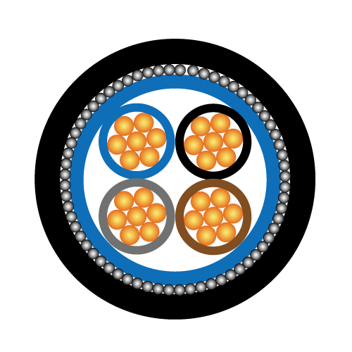
3.2.4. Control cables
- PVC insulation
- PVC inner sheath
- Metallic armor (single wire or tape, as per the requisition)
- PVC outer sheath
- Stranded and annealed copper conductor
3.2.5. Earthing Cables
- PVC insulation sheath
- Stranded and annealed copper conductor
3.2.6. The conductor properties and insulation, filler, binder, sheath, armoring and over sheath shall conform to the applicable sections of the referenced standards and codes herein.
3.2.7. Cables shall have all or some of the following special characteristics as specified in the requisition:
- Hydrocarbon resistant.
- Non-flame propagation.
- Non-fire propagation.
- Fire resistance.
- Low production corrosion gas.
- Low production of toxic gas.
- Low production of opaque-smoke.
3.3. Conductors
3.3.1. LV Conductors shall be plain annealed stranded copper in accordance with IEC 60228. Conductor sizes up to and including 6 mm2 can be solid copper. Conductor sizes 10 mm2 up to 50 mm2 will be stranded annealed copper (circular). Conductor sizes 50 mm2 and larger will be stranded annealed copper (sector shaped).
3.3.2. MV Conductors shall be circular plain annealed stranded copper conforming to class 2 of IEC 60228.
3.3.3. Insulation of low voltage cables shall generally be PVC. Cross Linked Polyethylene (XLPE) insulation may be quoted as an alternative proposal. The insulation thickness shall be according to IEC 60502-1.
3.3.4. The insulation of medium voltage and high voltage cables shall be extruded Cross Linked Polyethylene (XLPE). The minimum thickness of the insulation shall be according to table 6 of IEC 60502-2.
3.3.5. Conductors in the same cable shall be all same size except when four-core cable with reduces neutral is specified.
3.3.6. The insulation screen of medium voltage and high voltage cables shall consist of a non-metallic semi-conducting layer in combination with a metallic layer. The non-metallic layer shall be extruded directly upon the insulation of each core and shall consist of either a bonded or strippable semiconducting compound. The metallic layer shall consist of a tape, or a braid, or a concentric layer of wires, conforming to the recommendations of IEC 60502-2.
3.3.7. The metallic layer of medium voltage and high voltage cables shall be copper or other nonmagnetic metal of manufacturer standard, with a thickness of not less than 75 m and shall be applied with 15% overlap over the non-metallic layer.
3.3.8. For LV cables medium voltage and high voltage cables when necessary to obtain circular form of cables, suitable interstice material such as jute string or polypropylene string shall be used.
3.3.9. For MV cables Cores shall be laid up together such that the metallic layers of the insulation screen of the cores are in contact with each other. The interstices between the cores shall be filled with suitable material compatible with the XLPE insulation and operating temperature of the cables.
3.3.10. Laid up cores, together with fillers shall be lapped with suitable binder tape/s in accordance with manufacturer’s standard. The tapes shall be non-hygroscopic.
3.3.11. The metallic sheath shall consist of lead or lead alloy and shall be applied as a reasonably tight-fitting seamless tube. The nominal thickness of the lead sheath shall be calculated by the formulas recommended in IEC 60502-2 and shall in no case be less than 1.2 mm. If approved by NIOEC representative, for cables which will be installed on trays or will be buried in places where the presence of hydrocarbon is not foreseen lead sheath may be replaced by other metallic sheath/s. In such cases the metallic sheath/s may consist of one or two layer/s of bronze tape/s or equivalent metallic tape/s of manufacturer standard. The total thickness of such metallic sheath shall not be less than the calculated thickness for lead sheath according to the recommended formulas of IEC 60502-2.
3.3.12. The armor shall be galvanized round steel wire supplemented by a helix of galvanized steel tape to keep the armor wires tight. At the discretion of NIOEC representative, such galvanized steel tape may be eliminated. Flat wire armor is not desirable, however it could be considered upon the approval of NIOEC representative. The minimum dimensions of the armor wires shall be in accordance with the requirements of IEC 60502-2. The thickness of the galvanized steel tape shall be at least 0.3 mm. For single core cables the armor shall be made of non-magnetic materials.
3.3.13. The outer sheath over the armor shall be extruded black PVC complying with the requirements of IEC 60502-1. To protect the cables against rodent and termite attack, suitable chemicals shall be added to PVC over sheath.
3.3.14. For cables to be installed on trays, as indicated in data sheet, the over sheath shall be made of flame retardant PVC or an elastomeric compound which satisfies the requirements of the latest edition of IEC publication series No 60332.
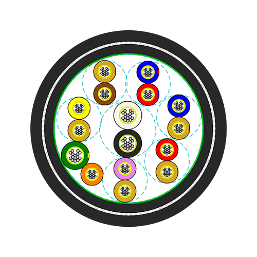
3.3.15. Control cables are used for the purpose of control, indication and protection of electrical equipment in particular, electric motors. Control cables shall be multi-core. The numbers of cores required, will be indicted in data sheet.
3.3.16. The cross sectional areas of the cable conductors shall be as per IEC. Cable nominal size shall be 1.5, 2.5, 4, 6, 10, 16, 25, 35, 50, 70, 95, 120, 150, 185, 240, 300, 400, 500, 630, 800, 1000 (unit in mm2).
3.3.17. Minimum conductor size shall be as follows:
- MV power circuits: 50 mm2
- LV power circuits: 2.5 mm2
- Control circuits: 2.5 mm2
3.3.18. The maximum conductor cross section of the low voltage power cables shall be limited to 240 mm2 for 3 and 4 core cables and 400 mm2 for single core cables.
3.3.19. The maximum conductor cross section of the medium voltage and high voltage power cables shall be limited to 240 mm2 for three core cables and 400 mm2 for single core cables.
3.4. Neutral and Protective Conductor
3.4.1. LV power and control cables shall have a neutral and/or protective conductor which is made of stranded and annealed copper, if specified in the data sheets. The cross-sectional area of the protective conductor shall be not less than the appropriate value shown below.
Cross-sectional area of phase conductors of the installation (mm2) |
Minimum cross-sectional area of |
|
S ≤ 16 |
S |
Where, S is cross-sectional area of phase conductor.
3.5. Metallic Armor
3.5.1. The armor type shall be wire armor or tape armor, which is specified in the data sheet. In case of wire armor, the galvanized steel round wire armor shall be applied.
3.5.2. The armor of single-core cables for use of AC circuits shall consist of non-magnetic material, such as aluminum.
3.6. Colors for Identification of Power and Control Cables
3.6.1. The color for identification of power and control cables shall be as follows.
1) Overall Sheath
- MV power cables: Red
- LV power cables: Black
- LV control cables: Gray
- Earthing: Green / Yellow
- DC Power Cable: Black
2) Core
- Single core: Black
- 2 cores: Red, Black
- 3 cores (Power): Red, Yellow, Blue
- 3 cores (Lighting): Blue, Black, Green/Yellow
- 3 cores (Control): Blue, Black, Brown
- 4 cores: Red, Yellow, Blue, Black
- 5 core (Lighting): Red, Yellow, Blue, Black, Green/Yellow
- 5 core or more: Number 1, 2, ... printed with white color on the black cores at adequate interval throughout the length.
3.6.2. If a protective conductor is included, the color of it shall be green/yellow.
3.6.3. The conductor insulation color of control cables shall be black with white identification.
3.6.4. In DC power systems red shall be used as positive conductor and black shall be used as negative conductor.
3.7. MV Power Cable Terminations
3.7.1. For MV power cables, the heat-shrink or shrink type termination materials shall be used.
3.8. Cable Joints
3.8.1. Cable joints are in general not allowed. Only in case that total length of a cable is so long that cable joint is required, suitable jointing kits shall be applied.
6. MARKING
6.1. Marking of Power and Control Cables
6.1.1. The color of the outer sheath of all low voltage power and control cables shall be black and the color of the outer sheath of all medium voltage and high voltage power cables shall be red. At least the following information shall be printed on the outer sheath of low voltage power and control cables at reasonable intervals according to manufacturer standard.
- Manufacturer’s name
- Year of manufacture
- Type of insulation
- Rated voltage
- Number of cores
- Size of conductors
- Length in each meter
- Other information requested in purchase order.
- Marking of Cable Drum
6.1.2. The cable drums shall be marked with the following information on the both sides of them.
- Type of cable
- Number of cores and nominal section area
- Total length of the cable contained in the drum
- Net weight
- Gross weight
- Direction of rotation of drum
- Position of end of cable winding
- Manufacturer’s name or trade mark
- Year of manufacturer
- Project number and requisition number
- Drum number
+852 6230 0392
Caledonian Cables
live:1cb87739a29fb08c