CALEDONIAN
Professional Cable Provider
 English
Quick Contact
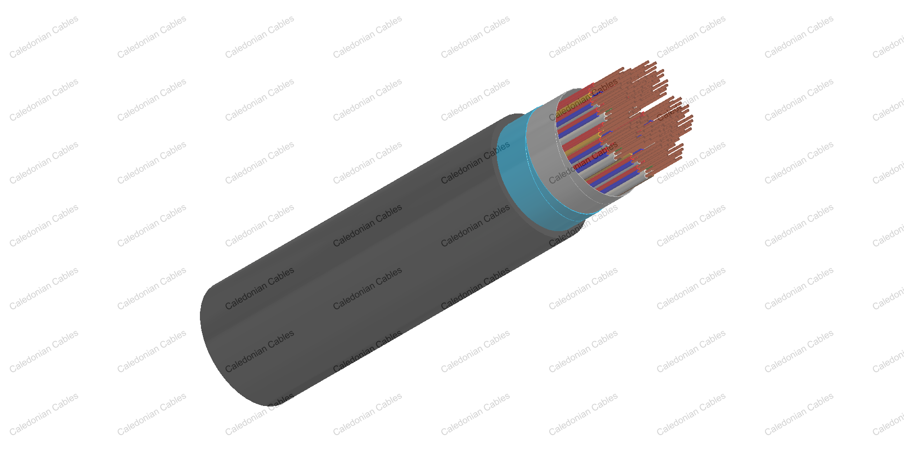
The cables are designed for use in access or trunk networks, from telephone exchange to subscriber area. The cables are suitable for installation in ducts, direct burial in the ground and also for aerial installation with integral suspension strand. Jelly filled construction is for subscriber’s cables installed underground or along the edge of pavement. An armoured option is offered for direct burial installations. A figure-8 self support option is offered for aerial installation.
• CW 1128 (Unscreened jelly filled cables)
• CW 1128/1179 (Screened jelly filled cables)
• CW 1128/1252 (Self supporting jelly filled cables)
• CW 1128/1198 (Steel wire armoured jelly filled cables)
• CW 1128/1179/1198 (Steel wire armoured screened jelly filled cables)
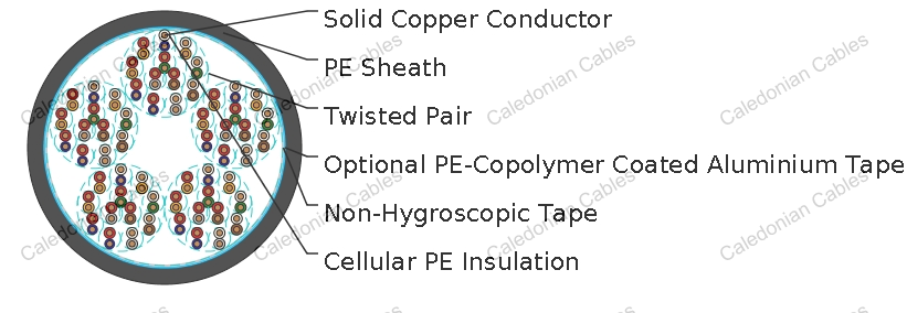
Solid annealed bare copper 0.4/0.5/0.6/0.63/0.9 mm as per class 1 of BS 6360/IEC 60228
Cellular polyethylene as per BS 6234/BS EN 50290-2-23/IEC 60708
Insulated conductors are twisted into pairs with varying lay length to minimize crosstalk
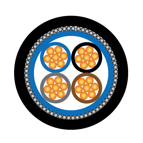
Twisted Pairs
Cables are composed of 10-pair units. Any extra pairs form a separate unit. Units are identified by colour coded binders. Standard construction is per CW 1128 given in Cable Make Up Chart below
One or more non-hygroscopic polyester tapes are helically or longitudinally laid with an overlap. These tapes furnish thermal, mechanical as well as high dielectric protection between shielding and individual conductors
Laminated sheath made of an aluminium tape (0.15mm) coated with PE-copolymer on one or both sides is applied longitudinally with overlap over the cable core to provide 100% electrical shielding coverage and ensures a barrier against water vapor
Black polyethylene compound
Galvanized steel wire armour is applied over an inner polyethylene sheath
The cable core interstices are filled with petroleum jelly to avoid longitudinal water penetration within the cable.
The water resistant filling compound is applied to the air space between non-hygroscopic tape and shield, shield and sheath within the cable core
Black low density polyethylene as per BS 6234/IEC 60708/ASTM D 1248 which is compounded to withstand exposure to sunlight, temperature variations, ground chemicals and other environmental contaminants
Ripcord may be provided for slitting the sheath longitudinally to facilitate its removal
One tinned copper drain wire may be longitudinally laid to ensure electrical continuity of the screen
Electrical Properties
|
Nominal Conductor Diameter |
mm |
0.4 |
0.5 |
0.6 |
0.63 |
0.9 |
|
Conductor Gauge Size |
AWG |
26 |
24 |
- |
22 |
19 |
|
Conductor Size |
mm2 |
0.126 |
0.196 |
0.283 |
0.312 |
0.636 |
|
Maximum Average Conductor Resistance @20°C |
Ω/km |
143 |
91 |
63 |
58 |
28 |
|
Minimum Insulation Resistance @500V DC |
MΩ.km |
1500 |
1500 |
1500 |
1500 |
1500 |
|
Maximum Average Mutual Capacitance @800Hz* |
nF/km |
56 |
56 |
42 |
56 |
59 |
|
Maximum Individual Mutual Capacitance @800Hz |
nF/km |
64 |
64 |
46 |
64 |
65 |
| Maximum Individual Capacitance Unbalance @800Hz pair-to-pair |
pF/500m |
275 |
275 |
275 |
275 |
275 |
|
Maximum Conductor Loop Resistance @20°C |
Ω/km |
300 |
192 |
130 |
114 |
60 |
|
Impedance @1KHz |
Ω |
994 |
796 |
665 |
660 |
445 |
|
Impedance @100KHz |
Ω |
147 |
134 |
127 |
125 |
122 |
|
Impedance @512KHz |
Ω |
120 |
118 |
117.5 |
117 |
116 |
|
Impedance @1MHz |
Ω |
117 |
115 |
114.5 |
114 |
113 |
|
Maximum Average Attenuation @0.8KHz |
dB/km |
1.64 |
1.30 |
1.1 |
1.04 |
0.74 |
|
Maximum Average Attenuation @1KHz |
dB/km |
1.68 |
1.35 |
1.14 |
1.08 |
0.76 |
|
Maximum Average Attenuation @3KHz |
dB/km |
3.18 |
2.52 |
2.3 |
2.01 |
1.42 |
|
Maximum Average Attenuation @150KHz |
dB/km |
11.4 |
8.3 |
7.2 |
6.2 |
4.4 |
|
Maximum Average Attenuation @772KHz |
dB/km |
24.3 |
19.4 |
17.4 |
15.4 |
10.8 |
|
Maximum Average Attenuation @1000KHz |
dB/km |
27.1 |
21.4 |
18.5 |
17.5 |
12.8 |
|
Dielectric Strength Conductor to Conductor (3secs) |
V DC |
500 |
500 |
500 |
500 |
500 |
|
Nominal Insulation Thickness |
mm |
0.175 |
0.20 |
0.375 |
0.26 |
0.30 |
|
Nominal Insulated Conductor Diameter |
mm |
0.75 |
0.90 |
1.35 |
1.15 |
1.50 |
Remarks: For screened cables of 20 pairs or less the maximum average mutual capacitance values shall not apply and the
maximum for 99% shall be increased by 3nF.
Temperature range during operation (fixed state): -30°C – +70°C
Temperature range during installation (mobile state): -20°C – +50°C
Minimum bending radius: 10 x Overall Diameter (unarmoured cables);15 x Overall Diameter (armoured cables)
Colour Code
Standard colour code is per CW 1128 given in Colour Code Chart
|
Cabling Element No. |
a-wire |
b-wire |
|
1 |
WHITE |
BLUE |
|
2 |
WHITE |
ORANGE |
|
WHITE |
GREEN |
|
|
WHITE |
BROWN |
|
|
WHITE |
GREY |
|
|
RED |
BLUE |
|
|
7 |
RED |
ORANGE |
|
8 |
RED |
GREEN |
|
9 |
RED |
BROWN |
|
10 |
RED |
GREY |
| Unit Number | Binder Colour |
| 1 |
BLUE |
| 2 |
ORANGE |
| 3 |
GREEN |
| 4 |
BROWN |
| 5 |
GREY |
| 6 | WHITE |
| 7 | RED |
| 8 | BLACK |
| 9 | YELLOW |
| 10 | VIOLET |
|
Cable Size |
No. and Pair Size of Units in Centre and 1st Layer |
|
|
Centre |
1st Layer |
|
|
2 pairs |
1 X 2 |
|
|
5 pairs |
1 X 5 |
|
| 10 pairs | 1 X 10 |
|
| 20 pairs | 4 X 5 |
|
| 2 X 10 |
|
|
| 50 pairs | 5 X 10 |
|
| 1 X 10 |
4 X 10 |
|
| 100 pairs | 2 X 10 |
8 X 10 |
| 3 X 10 |
7 X 10 |
|
| 4 X 5 |
8 X 10 |
|
Note:
The two pair cable is manufactured as a
quad, coloured Orange, Green, White, and
Black in order of rotation
+852 6230 0392
Caledonian Cables
live:1cb87739a29fb08c