CALEDONIAN
Professional Cable Provider
 English
Quick Contact
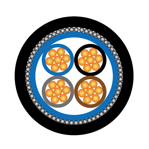


The single core cables are designed for distribution of electrical power with nominal voltage Uo/U ranging from 3.8/6.6KV to 19/33KV and frequency 50Hz. They are suitable for installation mostly in power supply stations, indoors and in cable ducts, outdoors, underground and in water as well as for installation on cable trays for industries, switchboards and power stations.
BS 6622
BS 7835 (LSZH)
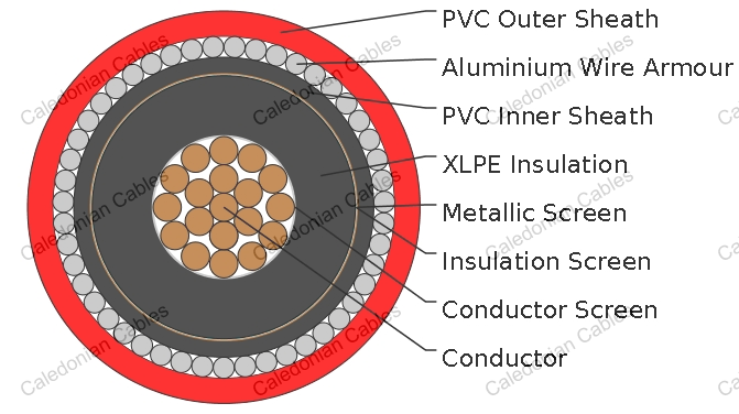
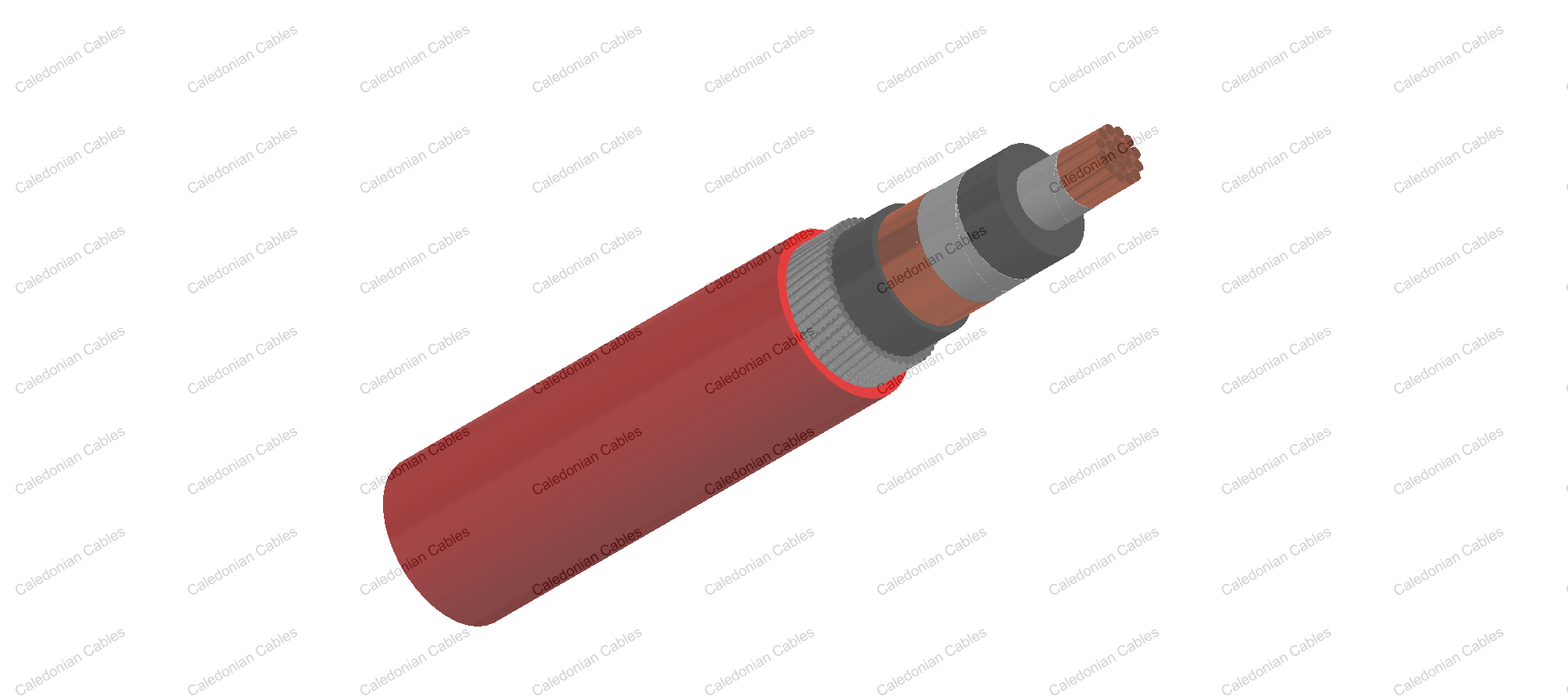
Conductor : Plain annealed copper or aluminium complying with IEC 60228/BS 6360. Copper conductors shall be stranded (class 2) and aluminium conductors shall be either solid or stranded (class 2).
Conductor Screen : Extruded layer of semi-conducting cross-linkable compound is applied over the conductor and shall cover the surface completely. The minimum thickness is 0.3mm and the maximum resistivity shall not exceed 500 Ohm-m at 90°C.
Insulation : Insulation is of cross-linked polyethylene compound XLPE (GP8) conforming to BS 7655-1.3 or EPR (GP7), conforming to BS 7655-1.2.
| Nom. Cross Section Area | Insulation Thickness at Nominal Voltage | ||||
|---|---|---|---|---|---|
| 3.8/6.6KV (Um=7.2KV) | 6.35/11KV (Um=12KV) | 8.7/15KV(Um=17.5KV) | 12.7/22KV(Um=24KV) | 19/33KV(Um=36KV) | |
| mm² | mm | mm | mm | mm | mm |
| 70 – 185 | 2.5 | 3.4 | 4.5 | 5.5 | 8.0 |
| 240 | 2.6 | 3.4 | 4.5 | 5.5 | 8.0 |
| 300 | 2.8 | 3.4 | 4.5 | 5.5 | 8.0 |
| 400 | 3.0 | 3.4 | 4.5 | 5.5 | 8.0 |
| Above 500 | 3.2 | 3.4 | 4.5 | 5.5 | 8.0 |
Insulaton Screen : Extruded layer of semi-conducting cross-linkable compound is applied over the insulation. The extruded semi-conducting layer shall consist of bonded or cold strippable semi-conducting compound capable of removal for jointing or terminating. As an option, a semi-conducting tape may be applied over the extruded semi-conducting layer as a bedding for the metallic layer. The minimum thickness is 0.3 mm and the maximum resistivity is 500 Ohm-m at 90°C. The screen is tightly fitted to the insulation to exclude all air voids and can be easily hand stripped on site.
Metallic Layer : The metallic layer shall consist of either copper tapes or a concentric layer of copper wires or a combination of tapes and wires. The metallic layer provides an earth fault current path, capable of withstanding fault current to earth of 1000A for one second at maximum temperature 160°C. Copper wires are applied over the conducting water blocking layer with a minimum diameter of 0.5mm. As an alternative, copper tape(s) with minimum thickness of 0.1mm can be applied with overlap. Total cross section of copper wire screen and copper tape screen layer are shown in Table 2a and 2b.
| Nominal Cross-Section of Cables | Total Cross Section | Max. DC Resistance of Copper Wire Screen at 20℃ | ||||
|---|---|---|---|---|---|---|
| 3.8/6.6KV (Um=7.2KV) | 6.35/11KV (Um=12KV) | 8.7/15KV (Um=17.5KV) | 12.7/22KV (Um=24KV) | 19/33KV (Um=36KV) | ||
| mm² | mm² | Ω | ||||
| 70 | 16 | 16 | 16 | 16 | 16 | 1.19 |
| 95 | 16 | 16 | 16 | 16 | 16 | 1.19 |
| 120 | 16 | 16 | 16 | 16 | 16 | 1.19 |
| 150 | 25 | 25 | 25 | 25 | 25 | 0.759 |
| 185 | 25 | 25 | 25 | 25 | 25 | 0.759 |
| 240 | 25 | 25 | 25 | 25 | 25 | 0.759 |
| 300 | 25 | 25 | 25 | 25 | 25 | 0.759 |
| 400 | 35 | 35 | 35 | 35 | 35 | 0.271 |
| 500 | 35 | 35 | 35 | 35 | 35 | 0.217 |
| 630 | 35 | 35 | 35 | 35 | 35 | 0.271 |
| Nominal Cross-Section of Conductor | Total Cross Section & Max DC Resistance | |||||||||
|---|---|---|---|---|---|---|---|---|---|---|
| 3.8/6.6KV (Um=7.2KV) | 6.35/11KV (Um=12KV) | 8.7/15KV (Um=17.5KV) | 12.7/22KV (Um=24KV) | 19/33KV (Um=36KV) | ||||||
| Total Cross Section | Max. DC Resistance at 20℃ | Total Cross Section | Max. DC Resistance at 20℃ | Total Cross Section | Max. DC Resistance at 20℃ | Total Cross Section | Max. DC Resistance at 20℃ | Total Cross Section | Max. DC Resistance at 20℃ | |
| mm² | mm² | Ω | mm² | Ω | mm² | Ω | mm² | Ω | mm² | Ω |
| 70 | 7.4 | 2.314 | 8.2 | 2.106 | 9.1 | 1.897 | 9.9 | 1.740 | 11.9 | 1.442 |
| 95 | 8.2 | 2.095 | 8.9 | 1.923 | 9.8 | 1.748 | 10.7 | 1.614 | 12.7 | 1.354 |
| 120 | 9.0 | 1.905 | 9.8 | 1.761 | 10.7 | 1.613 | 11.5 | 1.498 | 13.5 | 1.272 |
| 150 | 9.7 | 1.781 | 10.4 | 1.655 | 11.3 | 1.523 | 12.1 | 1.420 | 14.2 | 1.215 |
| 185 | 10.6 | 1.626 | 11.2 | 1.540 | 12.2 | 1.407 | 12.9 | 1.335 | 14.9 | 1.153 |
| 240 | 11.7 | 1.465 | 12.4 | 1.388 | 13.3 | 1.294 | 14.1 | 1.219 | 16.2 | 1.065 |
| 300 | 12.9 | 1.334 | 13.4 | 1.285 | 14.3 | 1.204 | 15.1 | 1.139 | 17.1 | 1.003 |
| 400 | 14.3 | 1.205 | 14.6 | 1.178 | 15.5 | 1.110 | 16.3 | 1.054 | 18.4 | 0.937 |
| 500 | 15.7 | 1.094 | 16.2 | 1.061 | 17.1 | 1.005 | 17.5 | 0.982 | 20.0 | 0.861 |
| 630 | 17.3 | 0.992 | 18.9 | 0.912 | 18.7 | 0.918 | 19.5 | 0.880 | 21.6 | 0.797 |
Separation Sheath (for armoured cable) : The separation sheath comprises a layer of extruded PVC, PE or LSZH. The nominal thickness is calculated by 0.02Du + 0.6mm where Du is the fictitious diameter under the sheath in mm. The nominal separation sheath thickness shall not be less than 1.2mm.
Armour (for armoured cable) : The armour consists of round aluminium wire with diameter specified as in Table 3.
| Fictitious Diameter Under the Armour | Armour Wire Diameter | |
|---|---|---|
| mm | mm | |
| > | < | |
| - | 25 | 1.6 |
| 25 | 35 | 2.0 |
| 35 | 60 | 2.5 |
| 60 | - | 3.15 |
Over Sheath : Overall sheath comprises a layer of extruded either PVC type 9 conforming to BS 7665-4.2 or MDPE type TS2 conforming to BS 7655-10.1. LSZH can be offered as an option. The over sheath is normally black in colour. When a DC voltage test is to be performed on the over sheath, a semi-conducting layer such as graphite coating shall be applied over the surface of the extruded over sheath. The nominal over sheath thickness is calculated by 0.035D+1.0 where D is the diameter immediately under the over sheath in mm. For cables with the over sheath not applied over the armour, the nominal over sheath thickness shall not be less than 1.4mm. And for cables with over sheath applied over the armour, the nominal over sheath thickness shall not be less than 1.8mm.
Operating Temperature : up to 90°C
Temperature Range : -5°C ( PVC or LSZH sheath ); -20°C ( PE sheath )
Short Circuit Temperature : 250°C (short circuit duration up to 5 seconds)
Bending Radius : 12 x OD
| Rated Voltage Uo/U | Operating Voltage (Um) | Testing Voltage (rms) |
|---|---|---|
| 3.8/6.6KV | 7.2KV | 15KV |
| 6.35/11KV | 12KV | 25.5KV |
| 8.7/15KV | 17.5KV | 35KV |
| 12.7/22KV | 24KV | 51KV |
| 19/33KV | 36KV | 76KV |
| Nom. Cross- Section Area | Nom. Insulation Thickness | Copper Wire Screen Area | Copper Tape Screen Area | Nom. Bedding Thickness | Nom. Armour Wire Diameter | Nom. Sheath Thickness | Approx. Overall Diameter | Approx. Weight | |
|---|---|---|---|---|---|---|---|---|---|
| CU | AL | ||||||||
| mm² | mm | mm² | mm² | mm | mm | mm | mm | kg/km | |
| 70 | 2.5 | 16 | 7.4 | 1.2 | 1.6 | 1.8 | 30.0 | 1740 | 1300 |
| 95 | 2.5 | 16 | 8.2 | 1.2 | 1.6 | 1.9 | 31.8 | 2030 | 1430 |
| 120 | 2.5 | 16 | 9.0 | 1.2 | 1.6 | 1.9 | 33.2 | 2310 | 1550 |
| 150 | 2.5 | 25 | 9.7 | 1.2 | 1.6 | 2.0 | 35.1 | 2660 | 1720 |
| 185 | 2.5 | 25 | 10.6 | 1.2 | 2.0 | 2.0 | 37.4 | 3120 | 1950 |
| 240 | 2.6 | 25 | 11.7 | 1.2 | 2.0 | 2.1 | 40.3 | 3740 | 2200 |
| 300 | 2.8 | 25 | 12.9 | 1.2 | 2.0 | 2.2 | 42.9 | 4400 | 2520 |
| 400 | 3.0 | 35 | 14.3 | 1.2 | 2.0 | 2.3 | 47.2 | 5490 | 2960 |
| 500 | 3.2 | 35 | 15.7 | 1.3 | 2.5 | 2.5 | 51.6 | 6760 | 3660 |
| 630 | 3.2 | 35 | 17.3 | 1.4 | 2.5 | 2.6 | 57.0 | 8200 | 4160 |
| Nom. Cross-Section Area | DC Resistance CU / AL | AC Resistance CU / AL | Short Circuit Rating of Conductor CU / AL 1 sec | Capacitance | Charging Current | Short Circuit Rating of Screen 1 sec | Reactance | Inductance | Impedance | ||||||
|---|---|---|---|---|---|---|---|---|---|---|---|---|---|---|---|
| Trefoil | Flat spaced | Trefoil | Flat Spaced | Trefoil | Flat Spaced | ||||||||||
| Copper Wire | Copper Tape | ||||||||||||||
| CU | AL | CU | AL | ||||||||||||
| mm² | µΩ/m | µΩ/m | kA | pF/m | mA/m | kA | µΩ/m | µΩ/m | nH/m | nH/m | µΩ/ m | µΩ/m | |||
| 70 | 268/443 | 343/568 | 9.8/6.3 | 371 | 0.45 | 1.96 | 1.09 | 115 | 173 | 370 | 550 | 364 | 583 | 386 | 597 |
| 95 | 193/320 | 248/410 | 13.3/8.5 | 417 | 0.50 | 1.96 | 1.20 | 110 | 168 | 350 | 540 | 272 | 427 | 300 | 446 |
| 120 | 153/253 | 196/325 | 17.2/11.0 | 459 | 0.55 | 1.96 | 1.32 | 107 | 165 | 340 | 520 | 225 | 345 | 257 | 367 |
| 150 | 124/206 | 159/265 | 21.2/13.5 | 494 | 0.59 | 3.06 | 1.41 | 103 | 161 | 330 | 510 | 193 | 287 | 229 | 313 |
| 185 | 99/164 | 128/211 | 26.6/17.0 | 543 | 0.65 | 3.06 | 1.54 | 100 | 158 | 320 | 500 | 165 | 237 | 206 | 267 |
| 240 | 75/125 | 98/161 | 34.9/22.3 | 583 | 0.70 | 3.06 | 1.71 | 97 | 155 | 310 | 490 | 140 | 191 | 185 | 226 |
| 300 | 60/100 | 80/130 | 43.8/28.0 | 602 | 0.72 | 3.06 | 1.88 | 95 | 153 | 300 | 490 | 126 | 163 | 174 | 203 |
| 400 | 47/78 | 64/102 | 57.3/36.6 | 627 | 0.75 | 4.29 | 2.08 | 92 | 150 | 290 | 480 | 113 | 141 | 164 | 184 |
| 500 | 36/60 | 51/81 | 72.3/46.2 | 654 | 0.79 | 4.29 | 2.30 | 90 | 149 | 290 | 470 | 105 | 124 | 158 | 171 |
| 630 | 28/47 | 42/64 | 91.2/58.3 | 726 | 0.87 | 4.29 | 2.53 | 87 | 145 | 280 | 460 | 97 | 110 | 151 | 160 |
| Nom. Cross- Section Area | Nom. Insulation Thickness | Copper Wire Screen Area | Copper Tape Screen Area | Nom. Bedding Thickness | Nom. Armour Wire Diameter | Nom.Sheath Thickness | Approx. Overall Diameter | Approx. Weight | |
|---|---|---|---|---|---|---|---|---|---|
| CU | AL | ||||||||
| mm² | mm | mm² | mm² | mm | mm | mm | mm | kg/km | |
| 70 | 3.4 | 16 | 8.2 | 1.2 | 1.6 | 1.9 | 32.0 | 1840 | 1400 |
| 95 | 3.4 | 16 | 8.9 | 1.2 | 1.6 | 1.9 | 33.6 | 2130 | 1530 |
| 120 | 3.4 | 16 | 9.8 | 1.2 | 1.6 | 2.0 | 35.2 | 2430 | 1670 |
| 150 | 3.4 | 25 | 10.4 | 1.2 | 1.6 | 2.1 | 37.9 | 2870 | 1930 |
| 185 | 3.4 | 25 | 11.2 | 1.2 | 2.0 | 2.1 | 39.4 | 3240 | 2080 |
| 240 | 3.4 | 25 | 12.4 | 1.2 | 2.0 | 2.2 | 42.1 | 3490 | 2330 |
| 300 | 3.4 | 25 | 13.4 | 1.2 | 2.0 | 2.2 | 44.1 | 4490 | 2560 |
| 400 | 3.4 | 35 | 14.6 | 1.2 | 2.0 | 2.4 | 48.2 | 5589 | 3040 |
| 500 | 3.4 | 35 | 16.2 | 1.3 | 2.5 | 2.5 | 52.0 | 6780 | 3680 |
| 630 | 3.4 | 35 | 18.9 | 1.4 | 2.5 | 2.6 | 57.4 | 8230 | 4200 |
| Nom. Cross-Section Area | DC Resistance CU / AL | AC Resistance CU / AL | Short Circuit Rating of Conductor CU / AL 1 sec | Capaci- tance | Charging Current | Short Circuit Rating of Screen 1 sec | Reactance | Inductance | Impedance | ||||||
|---|---|---|---|---|---|---|---|---|---|---|---|---|---|---|---|
| Trefoil | Flat Spaced | Trefoil | Flat Spaced | Trefoil | Flat Spaced | ||||||||||
| Copper Wire | Copper Tape | ||||||||||||||
| CU | AL | CU | AL | ||||||||||||
| mm² | µΩ/m | µΩ/m | kA | pF/m | mA/m | kA | µΩ/m | µΩ/m | nH/m | nH/m | µΩ/m | µΩ/m | |||
| 70 | 268/443 | 343/568 | 9.8/6.3 | 288 | 0.58 | 1.96 | 1.19 | 122 | 188 | 390 | 600 | 364 | 583 | 386 | 597 |
| 95 | 193/320 | 248/410 | 13.3/8.5 | 323 | 0.65 | 1.96 | 1.31 | 122 | 182 | 390 | 580 | 272 | 427 | 300 | 446 |
| 120 | 153/253 | 196//325 | 17.2/11.0 | 353 | 0.71 | 1.96 | 1.43 | 116 | 172 | 370 | 550 | 225 | 345 | 257 | 367 |
| 150 | 124/206 | 159/265 | 21.2/13.5 | 380 | 0.76 | 3.06 | 1.52 | 110 | 166 | 350 | 530 | 193 | 287 | 229 | 313 |
| 185 | 99/164 | 128/211 | 26.6/17.0 | 416 | 0.83 | 3.06 | 1.63 | 107 | 166 | 340 | 530 | 165 | 237 | 206 | 267 |
| 240 | 75/125 | 98/161 | 34.9/22.3 | 460 | 0.92 | 3.06 | 1.81 | 104 | 163 | 330 | 520 | 140 | 191 | 185 | 226 |
| 300 | 60/100 | 80/130 | 43.8/28.0 | 506 | 1.01 | 3.06 | 1.95 | 100 | 157 | 320 | 500 | 126 | 163 | 174 | 203 |
| 400 | 47/78 | 64/102 | 57.3/36.6 | 561 | 1.12 | 4.29 | 2.13 | 94 | 154 | 300 | 490 | 113 | 141 | 164 | 184 |
| 500 | 37/60 | 51/81 | 72.3/46.2 | 619 | 1.24 | 4.29 | 2.37 | 91 | 151 | 290 | 480 | 105 | 124 | 158 | 171 |
| 630 | 28/47 | 42/64 | 91.2/58.3 | 698 | 1.37 | 4.29 | 2.75 | 91 | 148 | 290 | 470 | 97 | 110 | 151 | 160 |
| Nom. Cross- Section Area | Nom. Insulation Thickness | Copper Wire Screen Area | Copper Tape Screen Area | Nom. Bedding Thickness | Nom. Armour Wire Diameter | Nom. Sheath Thickness | Approx. Overall Diameter | Approx. Weight | |
|---|---|---|---|---|---|---|---|---|---|
| CU | AL | ||||||||
| mm² | mm | mm² | mm² | mm | mm | mm | mm | kg/km | |
| 70 | 4.5 | 16 | 9.1 | 1.2 | 1.6 | 1.9 | 34.2 | 1970 | 1520 |
| 95 | 4.5 | 16 | 9.8 | 1.2 | 2.0 | 2.0 | 36.8 | 2370 | 1770 |
| 120 | 4.5 | 16 | 10.7 | 1.2 | 2.0 | 2.1 | 38.4 | 2670 | 1910 |
| 150 | 4.5 | 25 | 11.3 | 1.2 | 2.0 | 2.1 | 40.1 | 3020 | 2080 |
| 185 | 4.5 | 25 | 12.2 | 1.2 | 2.0 | 2.2 | 41.8 | 3420 | 2240 |
| 240 | 4.5 | 25 | 13.3 | 1.2 | 2.0 | 2.3 | 44.5 | 4050 | 2500 |
| 300 | 4.5 | 25 | 14.3 | 1.2 | 2.0 | 2.3 | 46.5 | 4680 | 2780 |
| 400 | 4.5 | 35 | 15.5 | 1.3 | 2.5 | 2.5 | 51.8 | 5970 | 3430 |
| 500 | 4.5 | 35 | 17.1 | 1.3 | 2.5 | 2.6 | 54.4 | 7010 | 3910 |
| 630 | 4.5 | 35 | 18.7 | 1.4 | 2.5 | 2.7 | 59.8 | 8480 | 4420 |
| Nom. Cross- Section Area | DC Resistance CU / AL | AC Resistance CU / AL | Short Circuit Rating of Conductor CU / AL 1 sec | Capacitance | Charging Current | Short Circuit Rating of Screen 1 sec | Reactance | Inductance | Impedance | ||||||
|---|---|---|---|---|---|---|---|---|---|---|---|---|---|---|---|
| Trefoil | Flat spaced | Trefoil | Flat Spaced | Trefoil | Flat Spaced | ||||||||||
| Copper Wire | Copper Tape | ||||||||||||||
| CU | AL | CU | AL | ||||||||||||
| mm² | µΩ/m | µΩ/m | kA | pF/m | mA/m | kA | µΩ/m | µΩ/m | nH/m | nH/m | µΩ/ m | µΩ/m | |||
| 70 | 268/443 | 343/568 | 9.8/6.3 | 232 | 0.63 | 1.96 | 1.32 | 132 | 188 | 420 | 600 | 364 | 583 | 386 | 597 |
| 95 | 193/320 | 248/410 | 13.3/8.5 | 258 | 0.70 | 1.96 | 1.44 | 126 | 182 | 400 | 580 | 272 | 427 | 300 | 446 |
| 120 | 153/253 | 196/325 | 17.2/11.0 | 281 | 0.77 | 1.96 | 1.56 | 119 | 179 | 380 | 570 | 225 | 345 | 257 | 367 |
| 150 | 124/206 | 159/265 | 21.2/13.5 | 301 | 0.82 | 3.06 | 1.65 | 113 | 176 | 360 | 560 | 193 | 287 | 229 | 313 |
| 185 | 99/164 | 128/211 | 26.6/17.0 | 329 | 0.90 | 3.06 | 1.79 | 110 | 170 | 350 | 540 | 165 | 237 | 206 | 267 |
| 240 | 75/125 | 98/161 | 34.9/22.3 | 363 | 0.99 | 3.06 | 1.94 | 107 | 166 | 340 | 530 | 140 | 191 | 185 | 226 |
| 300 | 60/100 | 80/130 | 43.8/28.0 | 398 | 1.09 | 3.06 | 2.09 | 104 | 160 | 330 | 510 | 126 | 163 | 174 | 203 |
| 400 | 47/78 | 64/102 | 57.3/36.6 | 439 | 1.20 | 4.29 | 2.26 | 97 | 157 | 310 | 500 | 113 | 141 | 164 | 184 |
| 500 | 37/60 | 51/81 | 72.3/46.2 | 483 | 1.32 | 4.29 | 2.50 | 94 | 154 | 300 | 490 | 105 | 124 | 158 | 171 |
| 630 | 28/47 | 42/64 | 91.2/58.3 | 534 | 1.46 | 4.29 | 2.73 | 91 | 151 | 290 | 480 | 97 | 110 | 151 | 160 |
| Nom. Cross- Section Area | Nom. Insulation Thickness | Copper Wire Screen Area | Copper Tape Screen Area | Nom.Bedding Thickness | Nom. Armour Wire Diameter | Nom. Sheath Thickness | Approx. Overall Diameter | Approx. Weight | |
|---|---|---|---|---|---|---|---|---|---|
| CU | AL | ||||||||
| mm² | mm | mm² | mm² | mm | mm | mm | mm | kg/km | |
| 70 | 5.5 | 16 | 9.9 | 1.2 | 2.0 | 2.0 | 37.2 | 2190 | 1750 |
| 95 | 5.5 | 16 | 10.7 | 1.2 | 2.0 | 2.1 | 39.0 | 2510 | 1900 |
| 120 | 5.5 | 16 | 11.5 | 1.2 | 2.0 | 2.1 | 40.4 | 2810 | 2040 |
| 150 | 5.5 | 25 | 12.1 | 1.2 | 2.0 | 2.2 | 42.3 | 3180 | 2240 |
| 185 | 5.5 | 25 | 12.9 | 1.2 | 2.0 | 2.2 | 43.8 | 3560 | 2380 |
| 240 | 5.5 | 25 | 14.1 | 1.2 | 2.0 | 2.3 | 46.5 | 4200 | 2640 |
| 300 | 5.5 | 25 | 15.1 | 1.3 | 2.5 | 2.4 | 49.9 | 5030 | 3130 |
| 400 | 5.5 | 35 | 16.3 | 1.3 | 2.5 | 2.5 | 53.8 | 6140 | 3600 |
| 500 | 5.5 | 35 | 17.5 | 1.4 | 2.5 | 2.6 | 56.6 | 7210 | 4100 |
| 630 | 5.5 | 35 | 19.5 | 1.4 | 2.5 | 2.8 | 62.0 | 8700 | 4650 |
| Nom. Cross-Section Area | DC Resistance CU / AL | AC Resistance CU / AL | Short Circuit Rating of Conductor CU / AL 1 sec | Capacitance | Charging Current | Short Circuit Rating of Screen 1 sec | Reactance | Inductance | Impedance | ||||||
|---|---|---|---|---|---|---|---|---|---|---|---|---|---|---|---|
| Copper Wire | Copper Tape | Trefoil | Flat Spaced | Trefoil | Flat Spaced | Trefoil | Flat Spaced | ||||||||
| CU | AL | CU | AL | ||||||||||||
| mm² | µΩ/m | µΩ/m | kA | pF/m | mA/m | kA | µΩ/m | µΩ/m | nH/m | nH/m | µΩ/m | µΩ/m | |||
| 70 | 268/443 | 343/568 | 9.8/6.3 | 200 | 0.8 | 1.96 | 1.44 | 135 | 195 | 430 | 620 | 364 | 583 | 386 | 597 |
| 95 | 193/320 | 248/410 | 13.3/8.5 | 222 | 0.9 | 1.96 | 1.56 | 129 | 188 | 410 | 600 | 272 | 427 | 300 | 446 |
| 120 | 153/253 | 196/325 | 17.2/11.0 | 241 | 0.9 | 1.96 | 1.68 | 122 | 182 | 390 | 580 | 225 | 345 | 257 | 367 |
| 150 | 124/206 | 159/265 | 21.2/13.5 | 257 | 1.0 | 3.06 | 1.77 | 116 | 176 | 370 | 560 | 193 | 287 | 229 | 313 |
| 185 | 99/164 | 128/211 | 26.6/17.0 | 280 | 1.0 | 3.06 | 1.88 | 116 | 173 | 370 | 550 | 165 | 237 | 206 | 267 |
| 240 | 75/125 | 98/161 | 34.9/22.3 | 307 | 1.1 | 3.06 | 2.06 | 110 | 170 | 350 | 540 | 140 | 191 | 185 | 226 |
| 300 | 60/100 | 80/130 | 43.8/28.0 | 336 | 1.2 | 3.06 | 2.21 | 107 | 166 | 340 | 530 | 126 | 163 | 174 | 203 |
| 400 | 47/78 | 64/102 | 57.3/36.6 | 370 | 1.3 | 4.29 | 2.38 | 100 | 160 | 320 | 510 | 113 | 141 | 164 | 184 |
| 500 | 37/60 | 51/81 | 72.3/46.2 | 406 | 1.4 | 4.29 | 2.56 | 97 | 154 | 310 | 490 | 105 | 124 | 158 | 171 |
| 630 | 28/47 | 42/64 | 91.2/58.3 | 449 | 1.5 | 4.29 | 2.85 | 94 | 151 | 300 | 480 | 97 | 110 | 151 | 160 |
| Nom. Cross-Section Area | Nom. Insulation Thickness | Copper Wire Screen Area | Copper Tape Screen Area | Nom.Bedding Thickness | Nom. Armour Wire Diameter | Nom. Sheath Thickness | Approx. Overall Diameter | Approx. Weight | |
|---|---|---|---|---|---|---|---|---|---|
| CU | AL | ||||||||
| mm² | mm | mm² | mm² | mm | mm | mm | mm | kg/km | |
| 70 | 8.0 | 16 | 11.9 | 1.2 | 2.0 | 2.2 | 42.6 | 2560 | 2120 |
| 95 | 8.0 | 16 | 12.7 | 1.2 | 2.0 | 2.3 | 44.4 | 2890 | 2290 |
| 120 | 8.0 | 16 | 13.5 | 1.2 | 2.0 | 2.3 | 45.8 | 3200 | 2430 |
| 150 | 8.0 | 25 | 14.2 | 1.3 | 2.5 | 2.4 | 48.9 | 3760 | 2830 |
| 185 | 8.0 | 25 | 14.9 | 1.3 | 2.5 | 2.5 | 50.6 | 4180 | 3010 |
| 240 | 8.0 | 25 | 16.2 | 1.3 | 2.5 | 2.5 | 53.1 | 4830 | 3270 |
| 300 | 8.0 | 25 | 17.1 | 1.4 | 2.5 | 2.6 | 55.5 | 5540 | 3630 |
| 400 | 8.0 | 35 | 18.4 | 1.4 | 2.5 | 2.7 | 59.4 | 6680 | 4130 |
| 500 | 8.0 | 35 | 20.0 | 1.5 | 2.5 | 2.8 | 62.2 | 7790 | 4690 |
| 630 | 8.0 | 35 | 21.6 | 1.5 | 2.5 | 2.9 | 67.4 | 9290 | 5220 |
| Nom. Cross-Section Area | DC Resistance CU / AL | AC Resistance CU / AL | Short Circuit Rating of Conductor CU / AL 1 sec | Capacitance | Charging Current | Short Circuit Rating of Screen 1 sec | Reactance | Inductance | Impedance | ||||||
|---|---|---|---|---|---|---|---|---|---|---|---|---|---|---|---|
| Trefoil | Flat Spaced | Trefoil | Flat Spaced | Trefoil | Flat Spaced | ||||||||||
| Copper Wire | Copper Tape | ||||||||||||||
| CU | AL | CU | AL | ||||||||||||
| mm² | µΩ/m | µΩ/m | kA | pF/m | mA/m | kA | µΩ/m | µΩ/m | nH/m | nH/m | µΩ/m | µΩ/m | |||
| 70 | 268/443 | 343/568 | 9.8/6.3 | 154 | 0.92 | 1.96 | 1.74 | 144 | 201 | 460 | 640 | 364 | 583 | 386 | 597 |
| 95 | 193/320 | 248/410 | 13.3/8.5 | 169 | 1.01 | 1.96 | 1.85 | 138 | 195 | 440 | 620 | 272 | 427 | 300 | 446 |
| 120 | 153/253 | 196/325 | 17.2/11.0 | 183 | 1.10 | 1.96 | 1.97 | 132 | 188 | 420 | 600 | 225 | 345 | 257 | 367 |
| 150 | 124/206 | 159/265 | 21.2/13.5 | 194 | 1.16 | 3.06 | 2.07 | 126 | 182 | 400 | 580 | 193 | 287 | 229 | 313 |
| 185 | 99/164 | 128/211 | 26.6/17.0 | 210 | 1.26 | 3.06 | 2.18 | 122 | 182 | 390 | 580 | 165 | 237 | 206 | 267 |
| 240 | 75/125 | 98/161 | 34.9/22.3 | 229 | 1.37 | 3.06 | 2.36 | 119 | 176 | 380 | 560 | 140 | 191 | 185 | 226 |
| 300 | 60/100 | 80/130 | 43.8/28.0 | 249 | 1.49 | 3.06 | 2.50 | 113 | 173 | 360 | 550 | 126 | 163 | 174 | 203 |
| 400 | 47/78 | 64/102 | 57.3/36.6 | 273 | 1.64 | 4.29 | 2.68 | 107 | 163 | 340 | 520 | 113 | 141 | 164 | 184 |
| 500 | 37/60 | 51/81 | 72.3/46.2 | 298 | 1.79 | 4.29 | 2.92 | 104 | 163 | 330 | 520 | 105 | 124 | 158 | 171 |
| 630 | 28/47 | 42/64 | 91.2/58.3 | 327 | 1.96 | 4.29 | 3.15 | 100 | 160 | 320 | 510 | 97 | 110 | 151 | 160 |
| Nom. Cross-Section Area | Ground | Duct | Air | |||||||||
|---|---|---|---|---|---|---|---|---|---|---|---|---|
| Trefoil Unarm’d/Arm’d | Flat Spaced Unarm’d/Arm’d | Trefoil Unarm’d/Arm’d | Flat Touching Unarm’d/Arm’d | Trefoil Unarm’d/Arm’d | Flat Spaced Unarm’d/Arm’d | |||||||
| CU | AL | CU | AL | CU | AL | CU | AL | CU | AL | CU | AL | |
| mm² | A | A | A | A | A | A | ||||||
| 70 | 270/270 | 210.210 | 280/280 | 215/215 | 270/260 | 215/210 | 270/270 | 210/210 | 285/310 | 225/240 | 370/370 | 290/290 |
| 95 | 320/320 | 250/250 | 335/335 | 260/260 | 320/305 | 255/245 | 325/325 | 250/250 | 360/375 | 280/295 | 455/460 | 350/355 |
| 120 | 360/360 | 280/280 | 380/380 | 295/295 | 360/340 | 285/275 | 370/370 | 285/285 | 415/430 | 320/355 | 520/530 | 410/410 |
| 150 | 410/410 | 320/315 | 430/430 | 330/330 | 400/375 | 315/300 | 415/410 | 320/320 | 470/490 | 365/380 | 600/600 | 465/465 |
| 185 | 460/455 | 360/355 | 485/485 | 375/375 | 440/410 | 350/335 | 465/460 | 360/360 | 540/550 | 425/435 | 690/690 | 530/530 |
| 240 | 530/520 | 415/405 | 560/560 | 440/440 | 505/460 | 405/380 | 540/540 | 420/420 | 640/650 | 500/510 | 820/820 | 640/630 |
| 300 | 600/580 | 475/455 | 640/640 | 495/495 | 560/500 | 455/420 | 610/610 | 475/470 | 740/740 | 580/580 | 940/940 | 730/730 |
| 400 | 680/650 | 540/510 | 730/730 | 570/570 | 610/530 | 510/455 | 690/690 | 540/540 | 840/840 | 670/670 | 1100/1100 | 860/860 |
| 500 | 750/710 | 610/570 | 830/830 | 650/650 | 680/570 | 570/500 | 790/780 | 620/620 | 940/930 | 790/770 | 1280/1280 | 1010/1010 |
| 630 | 830/760 | 680/640 | 940/940 | 750/750 | 750/620 | 640/550 | 890/890 | 710/700 | 1110/1040 | 910/880 | 1500/1480 | 1190/1180 |
| Nom. Cross-Section Area | Ground | Duct | Air | |||||||||
|---|---|---|---|---|---|---|---|---|---|---|---|---|
| Trefoil Unarm’d/Arm’d | Flat Spaced Unarm’d/Arm’d | Trefoil Unarm’d/Arm’d | Flat Touching Unarm’d/Arm’d | Trefoil Unarm’d/Arm’d | Flat Spaced Unarm’d/Arm’d | |||||||
| CU | AL | CU | AL | CU | AL | CU | AL | CU | AL | CU | AL | |
| mm² | A | A | A | A | A | A | ||||||
| 70 | 270/270 | 210/210 | 280/280 | 215/215 | 270/260 | 210/205 | 270/270 | 210/210 | 300/320 | 235/245 | 365/370 | 285/285 |
| 95 | 320/320 | 250/245 | 335/335 | 260/260 | 320/300 | 250/245 | 320/325 | 250/250 | 360/380 | 280/295 | 450/450 | 345/350 |
| 120 | 360/360 | 280/280 | 380/380 | 295/295 | 360/340 | 280/275 | 365/365 | 285/285 | 425/440 | 330/340 | 520/520 | 400/400 |
| 150 | 410/410 | 320/310 | 430/430 | 330/330 | 405/370 | 320/300 | 410/410 | 320/315 | 485/490 | 375/385 | 590/590 | 455/455 |
| 185 | 460/450 | 360/350 | 485/485 | 375/375 | 445/400 | 350/335 | 460/460 | 360/360 | 550/560 | 430/440 | 670/670 | 520/520 |
| 240 | 530/510 | 415/405 | 560/560 | 440/440 | 520/450 | 415/380 | 530/530 | 415/415 | 650/650 | 510/510 | 800/800 | 620/620 |
| 300 | 600/570 | 475/450 | 640/640 | 495/495 | 570/490 | 460/415 | 600/600 | 470/470 | 740/730 | 580/580 | 920/910 | 710/710 |
| 400 | 690/640 | 550/510 | 730/730 | 570/570 | 630/530 | 520/460 | 690/680 | 540/530 | 850/830 | 680/670 | 1070/1060 | 840/830 |
| 500 | 760/700 | 610/570 | 830/830 | 650/650 | 700/570 | 570/510 | 780/770 | 610/610 | 980/940 | 790/770 | 1250/1230 | 980/970 |
| 630 | 850/760 | 690/640 | 950/940 | 750/750 | 780/610 | 650/560 | 890/880 | 700/700 | 1130/1050 | 920/880 | 1450/1430 | 1060/1140 |
| Nom. Cross-Section Area | Ground | Duct | Air | |||||||||
|---|---|---|---|---|---|---|---|---|---|---|---|---|
| Trefoil Unarm’d/Arm’d | Flat Spaced Unarm’d/Arm’d | Trefoil Unarm’d/Arm’d | Flat Touching Unarm’d/Arm’d | Trefoil Unarm’d/Arm’d | Flat Spaced Unarm’d/Arm’d | |||||||
| CU | AL | CU | AL | CU | AL | CU | AL | CU | AL | CU | AL | |
| mm² | A | A | A | A | A | A | ||||||
| 70 | 270/270 | 210.210 | 280/280 | 215/215 | 270/260 | 210/205 | 270/270 | 210/210 | 300/320 | 235/245 | 365/370 | 285/285 |
| 95 | 320/320 | 250/245 | 335/335 | 260/260 | 320/300 | 250/245 | 320/325 | 250/250 | 360/380 | 280/295 | 450/450 | 345/350 |
| 120 | 360/360 | 280/280 | 380/380 | 295/295 | 360/340 | 280/275 | 365/365 | 285/285 | 425/440 | 330/340 | 520/520 | 400/400 |
| 150 | 410/410 | 320/310 | 430/430 | 330/330 | 405/370 | 320/300 | 410/410 | 320/315 | 485/490 | 375/385 | 590/590 | 455/455 |
| 185 | 460/450 | 360/350 | 485/485 | 375/375 | 445/400 | 350/335 | 460/460 | 360/360 | 550/560 | 430/440 | 670/670 | 520/520 |
| 240 | 530/510 | 415/405 | 560/560 | 440/440 | 520/450 | 415/380 | 530/530 | 415/415 | 650/650 | 510/510 | 800/800 | 620/620 |
| 300 | 600/570 | 475/450 | 640/640 | 495/495 | 570/490 | 460/415 | 600/600 | 470/470 | 740/730 | 580/580 | 920/910 | 710/710 |
| 400 | 690/640 | 550/510 | 730/730 | 570/570 | 630/530 | 520/460 | 690/680 | 540/530 | 850/830 | 680/670 | 1070/1060 | 840/830 |
| 500 | 760/700 | 610/570 | 830/830 | 650/650 | 700/570 | 570/510 | 780/770 | 610/610 | 980/940 | 790/770 | 1250/1230 | 980/970 |
| 630 | 850/760 | 690/640 | 940/940 | 750/750 | 780/610 | 650/560 | 890/880 | 700/700 | 1130/1050 | 920/880 | 1450/1430 | 1060/1140 |
Ground Temperature : 20°C
Ambient Temperature (air) : 30°C
Depth of Soil : 0.8m
Thermal Resistance of Soil : 1.5K•m/W
+852 6230 0392
Caledonian Cables
live:1cb87739a29fb08c