CALEDONIAN
Professional Cable Provider
 English
Quick Contact


This cable is designed for areas where the integrity of the electrical properties circuit is critical in maintaining power supply. Applications can be found in emergency lightings, control and power circuits, power stations, fire alarm systems, underground tunnels, communications systems, sewage treatment plants, lifts, escalators, and high-rise buildings.
Basic design to BS 7846
| Circuit Integrity | IEC 60331-21; BS 6387 CWZ; DIN VDE 0472-814(FE180); CEI 20-36/2-1; SS229-1; NBN C 30-004 (cat. F3); NF C32-070- 2.3(CR1) |
| System Circuit Integrity | DIN 4102-12, E30 depending on lay system |
| Flame Retardance (Single Vertical Wire Test) | EN 60332-1-2; IEC 60332-1-2; BS EN 60332-1-2; VDE 0482-332-1 ; NBN C 30-004 (cat. F1); NF C32-070-2.1(C2); CEI 20-35/1-2; EN 50265-2-1*; DIN VDE 0482-265-2-1* |
| Reduced Fire Propagation (Vertically-mounted bundled wires & cable test) | EN 60332-3-24 (cat. C); IEC 60332-3-24; BS EN 60332-3-24; VDE 0482-332-3; NBN C 30-004 (cat. F2); NF C32-070-2.2(C1); CEI 20-22/3-4; EN 50266-2-4*; DIN VDE 0482-266-2-4 |
| Halogen Free | IEC 60754-1; EN 50267-2-1; DIN VDE 0482-267-2-1; CEI 20-37/2-1 ; BS 6425-1* |
| No Corrosive Gas Emission | IEC 60754-2; EN 50267-2-2; DIN VDE 0482-267-2-2; CEI 20-37/2-2 ; BS 6425-2* |
| Minimum Smoke Emission | IEC 61034-1&2; EN 61034 -1&2; DIN VDE 0482-1034-1&2; CEI 20-37/3-1&2; EN 50268-1&2*; BS 7622-1&2* |
| No Toxic Gases | NES 02-713; NF C 20-454 |
Note: Asterisk * denotes superseded standard.
600/1000V
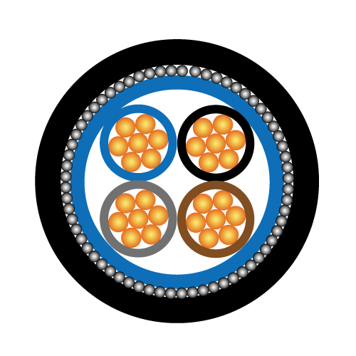
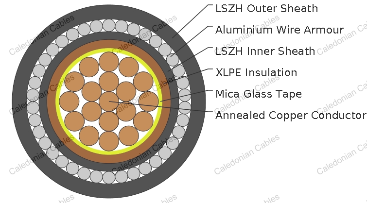
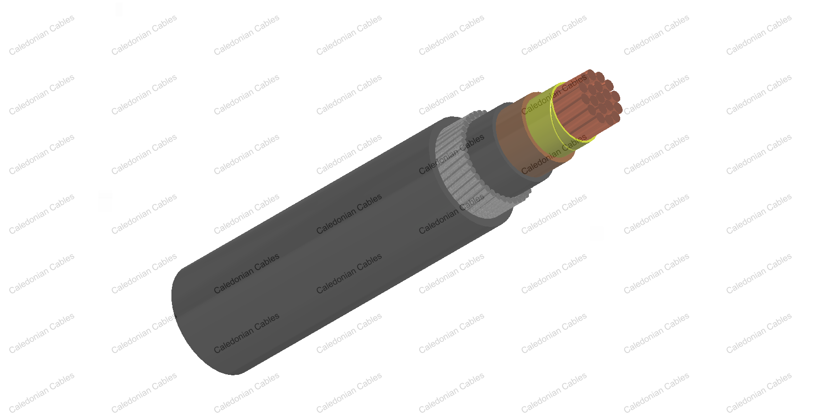
Conductor: Plain annealed copper wire, stranded according to IEC 60228 class 2. Insulation: Mica glass tape covered by extruded cross-linked XLPE compound Inner Sheath :Thermoplastic LSZH compound type LTS3 as per BS 7655-6.1 Armouring : Aluminum wire armour Outer Sheath:Thermoplastic LSZH compound type LTS3 as per BS 7655-6.1
Insulation Colour : Natural Sheath Colour: Black (other colors upon request)
Temperature Range During Operation: -30°C ~ 90°C Temperature Range during Installation : -5°C ~ 50°C Minimum Bending Radius: 8 x OD
| Dielectric Test: | 3500 V r.m.s. x 5’ ( core / core ) |
| Insulation Resistance | 1000 MΩ x km ( at 20°C ) |
| Short circuit Temperature | 250°C ( up to 5 secs ) |
| Cable Code | Conductor | Approx. Overall Diameter | Approx. Weight | |||
| No. of Core ×Cross Section | No./ Nominal Diameter of Strands | Dia. of Conductor | Nominal Insulation Thickness | |||
| mm2 | No./mm | mm | mm | mm | kg/km | |
| FFX300 1mRZ1MZ1-R 1G1.5 | 1×1.5 | 7/0.53 | 1.59 | 0.7 | - | - |
| FFX300 1mRZ1MZ1-R 1G2.5 | 1×2.5 | 7/0.67 | 2.01 | 0.7 | - | - |
| FFX300 1mRZ1MZ1-R 1G4 | 1×4 | 7/0.85 | 2.55 | 0.7 | - | - |
| FFX300 1mRZ1MZ1-R 1G6 | 1×6 | 7/1.04 | 3.12 | 0.7 | - | - |
| FFX300 1mRZ1MZ1-R 1G10 | 1×10 | 7/1.35 | 4.05 | 0.7 | - | - |
| FFX300 1mRZ1MZ1-R 1G16 | 1×16 | 7/1.70 | 5.1 | 0.7 | - | - |
| FFX300 1mRZ1MZ1-R 1G25 | 1×25 | 7/2.14 | 6.42 | 0.9 | - | - |
| FFX300 1mRZ1MZ1-R 1G35 | 1×35 | 19/1.53 | 7.65 | 0.9 | - | - |
| FFX300 1mRZ1MZ1-R 1G50 | 1×50 | 19/1.78 | 8.9 | 1 | 18.5 | 780 |
| FFX300 1mRZ1MZ1-R 1G70 | 1×70 | 19/2.14 | 10.7 | 1.1 | 20.5 | 1010 |
| FFX300 1mRZ1MZ1-R 1G95 | 1×95 | 19/2.52 | 12.6 | 1.1 | 23 | 1320 |
| FFX300 1mRZ1MZ1-R 1G120 | 1×120 | 37/2.03 | 14.21 | 1.2 | 24.5 | 1610 |
| FFX300 1mRZ1MZ1-R 1G150 | 1×150 | 37/2.25 | 15.75 | 1.4 | 27 | 2010 |
| FFX300 1mRZ1MZ1-R 1G185 | 1×185 | 37.2.52 | 17.64 | 1.6 | 29.5 | 2440 |
| FFX300 1mRZ1MZ1-R 1G240 | 1×240 | 61/2.25 | 20.25 | 1.7 | 34.5 | 3060 |
| FFX300 1mRZ1MZ1-R 1G300 | 1×300 | 61/2.52 | 22.68 | 1.8 | 36.9 | 3690 |
| FFX300 1mRZ1MZ1-R 1G400 | 1×400 | 65/2.85 | 25.65 | 2 | 41.5 | 4780 |
| FFX300 1mRZ1MZ1-R 1G500 | 1×500 | 61/3.20 | 28.8 | 2.2 | 45.5 | 5970 |
| FFX300 1mRZ1MZ1-R 1G630 | 1×630 | 127/2.52 | 32.76 | 2.4 | 50.5 | 7530 |
| FFX300 1mRZ1MZ1-R 1G800 | 1×800 | 127/2.85 | 37.05 | 2.6 | 56.8 | 9680 |
| FFX300 1mRZ1MZ1-R 1G1000 | 1×1000 | 127/3.20 | 41.6 | 2.8 | 61.5 | 11980 |
Conductor Operating Temperature : 90°C Ambient Temperature : 30°C
| Nominal Cross Section Area | Reference Method 1 (clipped direct) | Reference Method 11 (on perforated cable tray) | Reference Method 12 (free air) | In single-way ducts | Laid direct in ground | ||||
| 2 cables singlephase a.c. or d.c. flat and touching | 3 or 4 cables 3-phase a.c. flat and touching | 2 cables singlephase a.c. or d.c. flat and touching | 3 or 4 cables 3-phase a.c. flat and touching | 3 cables 3-phase a.c. trefoil touching | 2 cables singlephase a.c. or d.c. ducts touching | 3 cables 3-phase a.c. trefoil touching | 2 cables singlephase a.c. or d.c. touching | 3 cables 3-phase a.c. trefoil touching | |
| 1 | 2 | 3 | 4 | 5 | 6 | 7 | 8 | 9 | 10 |
| mm2 | A | A | A | A | A | A | A | A | A |
| 50 | 237 | 220 | 253 | 232 | 222 | 255 | 235 | 275 | 235 |
| 70 | 303 | 277 | 322 | 293 | 285 | 310 | 280 | 340 | 290 |
| 95 | 367 | 333 | 389 | 352 | 346 | 365 | 330 | 405 | 345 |
| 120 | 425 | 383 | 449 | 405 | 402 | 410 | 370 | 460 | 389 |
| 150 | 488 | 437 | 516 | 462 | 463 | 445 | 405 | 510 | 435 |
| 185 | 557 | 496 | 587 | 524 | 529 | 485 | 440 | 580 | 490 |
| 240 | 656 | 579 | 689 | 612 | 625 | 550 | 500 | 670 | 560 |
| 300 | 755 | 662 | 792 | 700 | 720 | 610 | 550 | 750 | 630 |
| 400 | 853 | 717 | 899 | 767 | 815 | 640 | 580 | 830 | 700 |
| 500 | 962 | 791 | 1016 | 851 | 918 | 690 | 620 | 910 | 770 |
| 630 | 1082 | 861 | 1146 | 935 | 1027 | 750 | 670 | 1000 | 840 |
| 800 | 1170 | 904 | 1246 | 987 | 1119 | 828 | 735 | 1117 | 931 |
| 1000 | 1261 | 961 | 1345 | 1055 | 1214 | 919 | 811 | 1254 | 1038 |
| Nominal Cross Section Area | 2 cables d.c. | 2 cables singlephase a.c. | 3 or 4 cables three-phase a.c. | 2 cables singlephase a.c. | 3 or 4 cables, 3-phase a.c. touching | |||||||||
| Reference Method 1 & 11 (touching) | Reference Method 1, 11 & 12 (in trefoil touching) | Reference Method 1 & 11 (Flat touching) | In ducts | In ground | In ducts | In ground | ||||||||
| 1 | 2 | 3 | 4 | 5 | 6 | 7 | 8 | 9 | ||||||
| mm2 | mV/ A/m | mV/ A/m | mV/ A/m | mV/ A/m | mV/ A/m | mV/ A/m | mV/ A/m | mV/ A/m | ||||||
| r | x | z | r | x | z | r | x | z | ||||||
| 50 | 0.98 | 0.99 | 0.21 | 1 | 0.86 | 0.18 | 0.87 | 0.84 | 0.25 | 0.88 | 1.1 | 0.99 | 0.93 | 0.86 |
| 70 | 0.67 | 0.68 | 0.2 | 0.71 | 0.59 | 0.17 | 0.62 | 0.6 | 0.25 | 0.65 | 0.8 | 0.7 | 0.7 | 0.61 |
| 95 | 0.49 | 0.51 | 0.195 | 0.55 | 0.44 | 0.17 | 0.47 | 0.46 | 0.24 | 0.52 | 0.65 | 0.53 | 0.56 | 0.46 |
| 120 | 0.39 | 0.41 | 0.19 | 0.45 | 0.35 | 0.165 | 0.39 | 0.38 | 0.24 | 0.44 | 0.55 | 0.43 | 0.48 | 0.37 |
| 150 | 0.31 | 0.33 | 0.185 | 0.38 | 0.29 | 0.16 | 0.33 | 0.31 | 0.23 | 0.39 | 0.5 | 0.37 | 0.43 | 0.32 |
| 185 | 0.25 | 0.27 | 0.185 | 0.33 | 0.23 | 0.16 | 0.28 | 0.26 | 0.23 | 0.34 | 0.45 | 0.31 | 0.39 | 0.27 |
| 240 | 0.195 | 0.21 | 0.18 | 0.28 | 0.18 | 0.155 | 0.24 | 0.21 | 0.22 | 0.3 | 0.4 | 0.26 | 0.35 | 0.23 |
| 300 | 0.155 | 0.17 | 0.175 | 0.25 | 0.145 | 0.15 | 0.21 | 0.17 | 0.22 | 0.28 | 0.37 | 0.24 | 0.32 | 0.21 |
| 400 | 0.115 | 0.145 | 0.17 | 0.22 | 0.125 | 0.15 | 0.195 | 0.16 | 0.21 | 0.27 | 0.35 | 0.21 | 0.3 | 0.19 |
| 500 | 0.093 | 0.125 | 0.17 | 0.21 | 0.105 | 0.145 | 0.18 | 0.145 | 0.2 | 0.25 | 0.33 | 0.2 | 0.28 | 0.18 |
| 630 | 0.073 | 0.105 | 0.165 | 0.195 | 0.092 | 0.145 | 0.17 | 0.135 | 0.195 | 0.24 | 0.3 | 0.19 | 0.26 | 0.17 |
| 800 | 0.056 | 0.09 | 0.16 | 0.19 | 0.086 | 0.14 | 0.165 | 0.13 | 0.18 | 0.23 | 0.28 | 0.18 | 0.24 | 0.16 |
| 1000 | 0.045 | 0.092 | 0.155 | 0.18 | 0.08 | 0.135 | 0.155 | 0.125 | 0.17 | 0.21 | 0.26 | 0.17 | 0.22 | 0.15 |
Note : r = conductor resistance at operating temperature x = reactance z = impedance
+852 6230 0392
Caledonian Cables
live:1cb87739a29fb08c