| Railway Cables | ||||||||||||
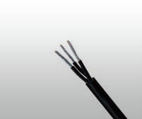
![]() 3GKW-DW/S EMC 0.6/1KV Dual Wall Screened Multicore
3GKW-DW/S EMC 0.6/1KV Dual Wall Screened Multicore
Applications :
- Multi core power and control cable designed for protected, fixed installation inside and outside railway vehicles for connecting fixed and moving parts in direct current and alternating voltage technology,especially converter technology.
Standards :
- BS 6853 -1a
- DIN 5510-1 1-4
- NFF 16-101 F0
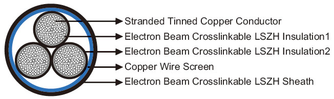
Construction :
- Conductors : Circular Class 5 stranded tinned copper to IEC60228/VDE 0295.
- Insulation1 : Electron beam crosslinkable LSZH compound.
- Insulation2 : Electron beam crosslinkable LSZH compound.
- Screen : Copper wire screen.
- Sheath : Electron beam crosslinkable LSZH compound.
Electrical Characteristics at 20 °C :
-
Nominal Conductor Cross Section mm² 0.25 0.5 0.75 1 1.5 2.5 Maximum Conductor Resistance Ω/km 88.5 40.1 26.7 20.0 13.7 8.21 Voltage Rating KV 0.6/1
Mechanical and Thermal Properties :
- Minimum Bending Radius : 4xOD (Static); 8xOD (Flexing).
- Temperature Range : -60℃ ~+120℃ (Static); -40℃ ~+90℃ (Flexing).
- Short Circuit Temperature : +280℃.
Dimensions and Weight :
| No. of cores& Nominal Conductor Cross Sectional Area No.×mm² |
Number and Nominal Diameter of Strands No./mm |
Nominal Insulation Thickness mm |
Nominal Overall Diameter mm |
Nominal Weight kg/km |
| 2×2×0.25 | 19/0.13 | 0.2 | 5.7 | 48 |
| 3×2×0.25 | 19/0.13 | 0.2 | 6.1 | 57 |
| 4×2×0.25 | 19/0.13 | 0.2 | 7.0 | 72 |
| 7×2×0.25 | 19/0.13 | 0.2 | 7.8 | 92 |
| 25×0.25 | 19/0.13 | 0.2 | 8.9 | 139 |
| 2×0.5 | 16/0.20 | 0.2 | 4.3 | 34 |
| 3×0.5 | 16/0.20 | 0.2 | 4.5 | 40 |
| 4×0.5 | 16/0.20 | 0.2 | 4.8 | 47 |
| 5×0.5 | 16/0.20 | 0.2 | 5.4 | 58 |
| 6×0.5 | 16/0.20 | 0.2 | 5.9 | 70 |
| 7×0.5 | 16/0.20 | 0.2 | 6.3 | 80 |
| 8×0.5 | 16/0.20 | 0.2 | 6.8 | 86 |
| 9×0.5 | 16/0.20 | 0.2 | 7.2 | 95 |
| 10×0.5 | 16/0.20 | 0.2 | 7.2 | 101 |
| 12×0.5 | 16/0.20 | 0.2 | 7.4 | 110 |
| 15×0.5 | 16/0.20 | 0.2 | 8.3 | 135 |
| 16×0.5 | 16/0.20 | 0.2 | 8.5 | 142 |
| 18×0.5 | 16/0.20 | 0.2 | 8.9 | 162 |
| 20×0.5 | 16/0.20 | 0.2 | 9.3 | 183 |
| 22×0.5 | 16/0.20 | 0.2 | 9.9 | 195 |
| 25×0.5 | 16/0.20 | 0.2 | 10.3 | 213 |
| 27×0.5 | 16/0.20 | 0.2 | 10.5 | 231 |
| 30×0.5 | 16/0.20 | 0.2 | 11.3 | 265 |
| 36×0.5 | 16/0.20 | 0.2 | 12.1 | 301 |
| 42×0.5 | 16/0.20 | 0.2 | 12.9 | 359 |
| 48×0.5 | 16/0.20 | 0.2 | 13.6 | 410 |
| 50×0.5 | 16/0.20 | 0.2 | 14.2 | 430 |
| 2×2×0.5 | 16/0.20 | 0.2 | 6.4 | 69 |
| 3×2×0.5 | 16/0.20 | 0.2 | 6.7 | 80 |
| 4×2×0.5 | 16/0.20 | 0.2 | 7.4 | 95 |
| 5×2×0.5 | 16/0.20 | 0.2 | 9.1 | 136 |
| 6×2×0.5 | 16/0.20 | 0.2 | 9.2 | 148 |
| 8×2×0.5 | 16/0.20 | 0.2 | 9.7 | 155 |
| 10×2×0.5 | 16/0.20 | 0.2 | 10.9 | 200 |
| 12×2×0.5 | 16/0.20 | 0.2 | 12.1 | 239 |
| 15×2×0.5 | 16/0.20 | 0.2 | 13.0 | 300 |
| 16×2×0.5 | 16/0.20 | 0.2 | 13.2 | 320 |
| 20×2×0.5 | 16/0.20 | 0.2 | 14.4 | 360 |
| 2×3×0.5 | 16/0.20 | 0.2 | 7.3 | 90 |
| 2×0.75 | 24/0.20 | 0.2 | 4.8 | 40 |
| 3×0.75 | 24/0.20 | 0.2 | 5.0 | 50 |
| 4×0.75 | 24/0.20 | 0.2 | 5.5 | 62 |
| 5×0.75 | 24/0.20 | 0.2 | 6.1 | 75 |
| 6×0.75 | 24/0.20 | 0.2 | 6.6 | 85 |
| 7×0.75 | 24/0.20 | 0.2 | 7.2 | 100 |
| 8×0.75 | 24/0.20 | 0.2 | 7.7 | 113 |
| 10×0.75 | 24/0.20 | 0.2 | 8.1 | 130 |
| 12×0.75 | 24/0.20 | 0.2 | 8.4 | 150 |
| 14×0.75 | 24/0.20 | 0.2 | 9.1 | 169 |
| 16×0.75 | 24/0.20 | 0.2 | 9.7 | 206 |
| 18×0.75 | 24/0.20 | 0.2 | 10.1 | 230 |
| 20×0.75 | 24/0.20 | 0.2 | 11.1 | 256 |
| 24×0.75 | 24/0.20 | 0.2 | 12.0 | 294 |
| 25×0.75 | 24/0.20 | 0.2 | 12.3 | 300 |
| 2×2×0.75 | 24/0.20 | 0.2 | 7.1 | 85 |
| 3×2×0.75 | 24/0.20 | 0.2 | 7.6 | 109 |
| 4×2×0.75 | 24/0.20 | 0.2 | 9.9 | 143 |
| 5×2×0.75 | 24/0.20 | 0.2 | 10.7 | 182 |
| 6×2×0.75 | 24/0.20 | 0.2 | 11.9 | 226 |
| 7×2×0.75 | 24/0.20 | 0.2 | 13.2 | 279 |
| 8×2×0.75 | 24/0.20 | 0.2 | 13.4 | 291 |
| 10×2×0.75 | 24/0.20 | 0.2 | 14.8 | 333 |
| 3×3×0.75 | 24/0.20 | 0.2 | 8.9 | 151 |
| 5×4×0.75 | 24/0.20 | 0.2 | 12.8 | 288 |
| 2×1.0 | 32/0.20 | 0.2 | 5.0 | 50 |
| 3×1.0 | 32/0.20 | 0.2 | 5.5 | 60 |
| 4×1.0 | 32/0.20 | 0.2 | 5.8 | 72 |
| 5×1.0 | 32/0.20 | 0.2 | 6.6 | 88 |
| 6×1.0 | 32/0.20 | 0.2 | 7.3 | 114 |
| 7×1.0 | 32/0.20 | 0.2 | 7.9 | 133 |
| 8×1.0 | 32/0.20 | 0.2 | 8.5 | 150 |
| 9×1.0 | 32/0.20 | 0.2 | 8.7 | 160 |
| 10×1.0 | 32/0.20 | 0.2 | 8.9 | 168 |
| 12×1.0 | 32/0.20 | 0.2 | 9.2 | 188 |
| 16×1.0 | 32/0.20 | 0.2 | 10.5 | 250 |
| 18×1.0 | 32/0.20 | 0.2 | 11.2 | 275 |
| 25×1.0 | 32/0.20 | 0.2 | 12.7 | 355 |
| 27×1.0 | 32/0.20 | 0.2 | 13.3 | 395 |
| 30×1.0 | 32/0.20 | 0.2 | 13.8 | 450 |
| 36×1.0 | 32/0.20 | 0.2 | 15.1 | 530 |
| 42×1.0 | 32/0.20 | 0.2 | 16.3 | 604 |
| 50×1.0 | 32/0.20 | 0.2 | 17.8 | 690 |
| 2×2×1.0 | 32/0.20 | 0.2 | 7.8 | 107 |
| 4×2×1.0 | 32/0.20 | 0.2 | 9.4 | 128 |
| 6×2×1.0 | 32/0.20 | 0.2 | 11.6 | 239 |
| 12×2×1.0 | 32/0.20 | 0.2 | 14.3 | 400 |
| 4×3×1.0 | 32/0.20 | 0.2 | 11.5 | 230 |
| 3×4×1.0 | 32/0.20 | 0.2 | 11.3 | 245 |
| 4×4×1.0 | 32/0.20 | 0.2 | 12.5 | 265 |
| 2×1.5 | 30/0.25 | 0.3 | 5.8 | 70 |
| 3×1.5 | 30/0.25 | 0.3 | 6.1 | 81 |
| 4×1.5 | 30/0.25 | 0.3 | 6.7 | 100 |
| 5×1.5 | 30/0.25 | 0.3 | 7.7 | 134 |
| 6×1.5 | 30/0.25 | 0.3 | 8.3 | 153 |
| 7×1.5 | 30/0.25 | 0.3 | 9.1 | 184 |
| 8×1.5 | 30/0.25 | 0.3 | 10.3 | 222 |
| 9×1.5 | 30/0.25 | 0.3 | 10.4 | 234 |
| 10×1.5 | 30/0.25 | 0.3 | 10.5 | 240 |
| 12×1.5 | 30/0.25 | 0.3 | 10.9 | 268 |
| 16×1.5 | 30/0.25 | 0.3 | 12.5 | 364 |
| 18×1.5 | 30/0.25 | 0.3 | 13.2 | 405 |
| 25×1.5 | 30/0.25 | 0.3 | 15.8 | 562 |
| 48×1.5 | 30/0.25 | 0.3 | 20.7 | 988 |
| 2×2×1.5 | 30/0.25 | 0.3 | 9.2 | 153 |
| 3×2×1.5 | 30/0.25 | 0.3 | 9.8 | 205 |
| 7×2×1.5 | 30/0.25 | 0.3 | 12.6 | 330 |
| 2×2.5 | 50/0.25 | 0.3 | 7.0 | 105 |
| 3×2.5 | 50/0.25 | 0.3 | 7.6 | 130 |
| 4×2.5 | 50/0.25 | 0.3 | 8.4 | 170 |
| 5×2.5 | 50/0.25 | 0.3 | 9.4 | 190 |
| 6×2.5 | 50/0.25 | 0.3 | 10.3 | 225 |
| 7×2.5 | 50/0.25 | 0.3 | 11.4 | 270 |
| 8×2.5 | 50/0.25 | 0.3 | 12.6 | 343 |
| 10×2.5 | 50/0.25 | 0.3 | 13.2 | 370 |
| 12×2.5 | 50/0.25 | 0.3 | 13.6 | 420 |
| 16×2.5 | 50/0.25 | 0.3 | 15.6 | 560 |
| 18×2.5 | 50/0.25 | 0.3 | 16.6 | 620 |
| 25×2.5 | 50/0.25 | 0.3 | 19.3 | 834 |
| 27×2.5 | 50/0.25 | 0.3 | 20.5 | 870 |
| 48×2.5 | 50/0.25 | 0.3 | 25.6 | 1560 |