| Firetox Flame Retardant Cables | |||
![]() Firetox Flame Retardant Cables
Firetox Flame Retardant Cables
600/1000V XLPE Insulated, LSZH Sheathed, Armoured Power Cables ((2-4cores)FTX400 1RZ1-R (CU/XLPE/LSZH 600/1000V Class 2)
|
|||||||||||||||||||||||||||||||||||||||||||||||||||||||||||||||||||||||||||||||||||||||||||||||||||||||||||||||||||||||||||||||||||||||||||||||||||||||||||||||||||||||||||||||||||||||||||||||||||||||||||||||||||||||||||||||||||||||||||||||||||||||||||||||||||||||||||||||||||||||||||||||||||||||||||||||||||||||||||||||||||||||||||||||||||||||||||||||||||||||||||||||||||||||||||||||||||||||||||||||||||||||||||||||||||||||||||||||||||||||||||||||||||||||||||||||||||||||||||||||||||||||||||||||||||||||||||||||||||||||||||||||||||||||||||||||||||||||||||||||||||||||||||||||||||||||||||||||||||||||||||||||||||||||||||||||||||||||||||||||||||||||||||||||||||||||||||||||||||||||||||||||||||||||||||||||||||||||||||||||||||||||||||||||||||||||||||||||||||||||||||||||||||||||||||||||||||||||||||||||||||||||||||||||||||||||||||||||||||||||||||||||||||||||||||||||||||||||||||||||||||||||||||||||||||||||||||||||||||||||||||||||||||||||||||||||||||||||||||||||||||||||||||||||||||||||||||||||||||||||
Flame Retardance (Single Vertical |
EN 60332-1-2; IEC 60332-1-2; BS EN 60332-1-2; VDE |
Reduced Fire Propagation |
EN 60332-3-24 (cat. C); IEC 60332-3-24; BS EN 60332-3-24; VDE 0482-332-3; NBN C 30-004 (cat. F2); NF C32-070-2.2(C1); CEI 20-22/3-4; EN 50266-2-4*; DIN VDE 0482-266-2-4 |
Halogen Free |
IEC 60754-1; EN 50267-2-1; DIN VDE 0482-267-2-1; CEI 20-37/2-1 ; BS 6425-1* |
No Corrosive Gas Emission |
IEC 60754-2; EN 50267-2-2; DIN VDE 0482-267-2-2; CEI 20-37/2-2 ; BS 6425-2* |
minimum Smoke Emission |
IEC 61034-1&2; EN 61034 -1&2; DIN VDE 0482-1034-1&2; CEI 20-37/3-1&2; EN 50268-1&2*; BS 7622-1&2* |
No Toxic gases |
NES 02-713; NF C 20-454 |
Note: Asterisk * denotes superseded standard.
VOLTAGE RATING
600/1000V
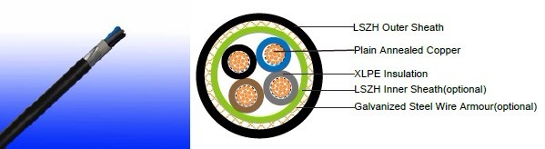
CABLE CONSTRUCTION
Conductor: Plain annealed copper wire, stranded according to IEC(EN) 60228 class 2.
Insulation: Extruded cross-linked XLPE compound.
Inner Sheath(optional): LSZH Compound
Armouring(optional): Galvanized Steel Wire
Outer Sheath: Thermoplastic LSZH compound type LTS3 as per BS 7655-6.1 (Thermosetting LSZH
compound type SW2-SW4 as per BS 7655-2.6 can be offered.)
COLOUR CODE
Insulation colour as per bs7671
|
with earth conductor |
without earth conductor |
2Cores |
- |
Brown,Blue |
3Cores |
Yellow/Green,Brown,Blue |
Brown,Gray,Black |
4Cores |
Yellow/Green,Brown,Gray,Black |
Brown,Gray,Black,Blue |
5Cores |
Yellow/Green,Brown,Gray,Black,Blue |
Brown,Gray,Black,Blue,Black |
above 5 Cores |
Yellow/Green,Black Numbered |
Black Numbered |
sheath colour: Black
Physical AND THERMAL PROPERTIES
Temperature range during operation: Max.90°C for XLPE
250°C in short-circuit for 5s max.
Minimum bending radius: 8 x Overall Diameter (unarmoured cable)
10 x Overall Diameter (armoured cable)
CONSTRUCTION PARAMETERS
| Conductor | FTX400 1RZ1-R | FTX400 1RZ1MZ1-R | ||||||
No. of |
No./ |
Nominal |
Unarmoured | Armoured | ||||
Nominal |
Approx. |
Diameter |
Armour |
Nominal |
Approx. |
|||
mm2 |
No./mm |
mm |
mm |
mm |
mm |
mm |
mm |
kg/km |
2x1.5 |
7/0.53 |
0.7 |
10.0 |
126 |
8.5 |
0.9 |
13.9 |
350 |
2x2.5 |
7/0.67 |
0.7 |
10.8 |
158 |
9.3 |
0.9 |
14.7 |
400 |
2x4 |
7/0.85 |
0.7 |
11.9 |
205 |
10.4 |
0.9 |
15.8 |
475 |
2x6 |
7/1.04 |
0.7 |
13.0 |
264 |
11.5 |
0.9 |
16.9 |
560 |
2x10 |
7/1.35 |
0.7 |
14.9 |
378 |
13.4 |
1.25 |
19.5 |
810 |
2x16 |
7/1.70 |
0.7 |
17.0 |
534 |
15.5 |
1.25 |
21.6 |
980 |
2x25 |
7/2.14 |
0.9 |
20.4 |
650 |
18.9 |
1.6 |
25.7 |
1410 |
2x35 |
7/2.52 |
0.9 |
22.7 |
880 |
21.2 |
1.6 |
28.0 |
1930 |
3x1.5 |
7/0.53 |
0.7 |
10.5 |
145 |
9.0 |
0.9 |
14.4 |
390 |
3x2.5 |
7/0.67 |
0.7 |
11.4 |
185 |
9.9 |
0.9 |
15.3 |
450 |
3x4 |
7/0.85 |
0.7 |
12.5 |
247 |
11.0 |
0.9 |
16.4 |
540 |
3x6 |
7/1.04 |
0.7 |
13.8 |
323 |
11.6 |
1.25 |
17.7 |
745 |
3x10 |
7/1.35 |
0.7 |
15.8 |
474 |
14.3 |
1.25 |
20.4 |
950 |
3x16 |
7/1.70 |
0.7 |
18.0 |
682 |
16.5 |
1.25 |
23.0 |
1250 |
3x25 |
7/2.14 |
0.9 |
21.7 |
910 |
20.2 |
1.6 |
27.0 |
1840 |
3x35 |
7/2.52 |
0.9 |
24.0 |
1180 |
22.4 |
1.6 |
29.2 |
2050 |
3x50(S) |
19/1.78 |
1.0 |
25.5 |
1600 |
24.2 |
1.6 |
31.2 |
2590 |
3x70(S) |
19/2.14 |
1.1 |
29.0 |
2240 |
28.2 |
2.0 |
36.2 |
3560 |
3x95(S) |
19/2.52 |
1.1 |
33.5 |
3050 |
31.7 |
2.0 |
40.1 |
4590 |
3x120(S) |
37/2.03 |
1.2 |
37.5 |
3800 |
36.0 |
2.0 |
44.6 |
5810 |
3x150(S) |
37/2.25 |
1.4 |
40.5 |
4640 |
39.5 |
2.5 |
49.5 |
6920 |
3x185(S) |
37/2.52 |
1.6 |
45.0 |
5870 |
43.3 |
2.5 |
53.5 |
8340 |
3x240(S) |
61/2.25 |
1.7 |
50.5 |
7670 |
48.4 |
2.5 |
59.0 |
10450 |
3x300(S) |
61/2.52 |
1.8 |
57.0 |
9460 |
54.4 |
2.5 |
65.4 |
12700 |
3x400(S) |
61/2.85 |
2.0 |
63.0 |
11945 |
57.8 |
2.5 |
70.0 |
15326 |
4x1.5 |
7/0.53 |
0.7 |
11.3 |
169 |
10.0 |
0.9 |
15.4 |
430 |
4x2.5 |
7/0.67 |
0.7 |
12.3 |
220 |
10.8 |
0.9 |
16.2 |
505 |
4x4 |
7/0.85 |
0.7 |
13.6 |
297 |
12.1 |
0.9 |
17.5 |
710 |
4x6 |
7/1.04 |
0.7 |
15.0 |
392 |
13.5 |
1.25 |
19.6 |
855 |
4x10 |
7/1.35 |
0.7 |
17.2 |
585 |
15.7 |
1.25 |
21.8 |
1120 |
4x16 |
7/1.70 |
0.7 |
19.7 |
851 |
18.2 |
1.6 |
25.0 |
1600 |
4x25 |
7/2.14 |
0.9 |
23.9 |
1200 |
22.4 |
1.6 |
29.2 |
2160 |
4x35(S) |
7/2.52 |
0.9 |
25.0 |
1600 |
24.4 |
1.6 |
31.4 |
2560 |
4x50(S) |
19/1.78 |
1.0 |
28.0 |
2200 |
28.0 |
1.6 |
35.2 |
3180 |
4x70(S) |
19/2.14 |
1.1 |
32.0 |
3050 |
32.2 |
2.0 |
40.6 |
4490 |
4x95(S) |
19/2.52 |
1.1 |
37.0 |
4070 |
36.0 |
2.0 |
44.6 |
5725 |
4x120(S) |
37/2.03 |
1.2 |
42.0 |
5915 |
38.0 |
2.5 |
50.0 |
7550 |
4x150(S) |
37/2.25 |
1.4 |
46.0 |
6350 |
42.8 |
2.5 |
53.0 |
8555 |
4x185(S) |
37/2.52 |
1.6 |
50.0 |
7890 |
48.4 |
2.5 |
59.0 |
10560 |
4x240(S) |
61/2.25 |
1.7 |
57.0 |
10400 |
55.0 |
2.5 |
66.0 |
13180 |
4x300(S) |
61/2.52 |
1.8 |
63.0 |
12810 |
59.6 |
2.5 |
71.0 |
16100 |
4x400(S) |
61/2.85 |
2.0 |
71.0 |
15869 |
66.1 |
3.15 |
79.4 |
20715 |
4x500(S) |
61/3.20 |
2.2 |
78.0 |
20300 |
74.6 |
3.15 |
88.5 |
25347 |
Electrical PROPERTIES
Conductor Operating Temperature : 90°C
Ambient Temperature : 30°C
FTX400 1RZ1-R
Current-Carrying Capacities (Amp)
Conductor cross- sectional area |
Reference |
Reference method 3 (enclosed in conduit on |
Reference method |
Reference method 11 (on a perforated cable tray, horizontal or vertical) |
Reference method 12 (free air) |
||||||
Horizontal flat spaced |
Vertical flat spaced |
Trefoil |
|||||||||
|
2 cables, single- phase a.c. or d.c. |
3 or 4 cables, |
2 cables, single- phase a.c. or d.c |
3 or 4 cables, |
2 cables, single- phase a.c. or d.c. flat and touching |
3 or 4 cables, |
2 cables, single- phase a.c. or d.c. or flat and touching |
3 or 4 cables, |
2 cables, single- phase a.c. or d.c. |
2 |
3 cables, trefoil |
1 |
2 |
3 |
4 |
5 |
6 |
7 |
8 |
9 |
10 |
11 |
12 |
mm2 |
A |
A |
A |
A |
A |
A |
A |
A |
A |
A |
A |
1.5 |
18 |
17 |
22 |
19 |
25 |
23 |
- |
- |
- |
- |
- |
2.5 |
24 |
23 |
30 |
26 |
34 |
31 |
- |
- |
- |
- |
- |
4 |
33 |
30 |
40 |
35 |
46 |
41 |
- |
- |
- |
- |
- |
6 |
43 |
39 |
51 |
45 |
59 |
54 |
- |
- |
- |
- |
- |
10 |
58 |
53 |
71 |
63 |
81 |
74 |
- |
- |
- |
- |
- |
16 |
76 |
70 |
95 |
85 |
109 |
99 |
- |
- |
- |
- |
- |
25 |
100 |
91 |
126 |
111 |
143 |
130 |
158 |
140 |
183 |
163 |
138 |
35 |
125 |
111 |
156 |
138 |
176 |
161 |
195 |
176 |
226 |
203 |
171 |
50 |
149 |
135 |
189 |
168 |
228 |
209 |
293 |
215 |
274 |
246 |
209 |
70 |
189 |
170 |
240 |
214 |
293 |
268 |
308 |
279 |
351 |
318 |
270 |
95 |
228 |
205 |
290 |
259 |
355 |
326 |
375 |
341 |
426 |
389 |
330 |
120 |
263 |
235 |
336 |
299 |
413 |
379 |
436 |
398 |
495 |
453 |
385 |
150 |
300 |
270 |
375 |
328 |
476 |
436 |
505 |
461 |
570 |
524 |
445 |
185 |
341 |
306 |
426 |
370 |
545 |
500 |
579 |
530 |
651 |
600 |
511 |
240 |
400 |
358 |
500 |
433 |
644 |
590 |
686 |
630 |
769 |
711 |
606 |
300 |
459 |
410 |
573 |
493 |
743 |
681 |
794 |
730 |
886 |
824 |
701 |
400 |
- |
- |
684 |
584 |
868 |
793 |
915 |
849 |
1065 |
994 |
820 |
500 |
- |
- |
783 |
666 |
990 |
904 |
1044 |
973 |
1228 |
1150 |
936 |
Voltage Drop (Per Amp Per Meter)
| Size of conductor |
2 cables d.c. |
2 cables, single-phase a.c. | 3 or 4 cables, 3-phase a.c. | |||||||||||||
| Ref. Methods 3 and 4 (enclosed in conduit etc, in or on a wall) |
Ref. Methods 1 and 11 (clipped direct or on trays touching) |
Ref. Methods 3 and 4 (enclosed in conduit etc, in or on a wall) |
Ref. Methods 1, 11 and 12 (in trefoil) |
Ref. Methods 1 and 11(Flat and touching) |
||||||||||||
1 |
2 |
3 |
4 |
5 |
6 |
7 |
||||||||||
mm2 |
mV/A/m |
mV/A/m |
mV/A/m |
mV/A/m |
mV/A/m |
mV/A/m |
||||||||||
1.5 |
31 |
31 |
27 |
27 |
27 |
27 |
||||||||||
2.5 |
19 |
19 |
16 |
16 |
16 |
16 |
||||||||||
4 |
33 |
12 |
10 |
10 |
10 |
10 |
||||||||||
6 |
7.8 |
7.9 |
6.8 |
6.8 |
6.8 |
6.8 |
||||||||||
10 |
4.7 |
4.7 |
4.7 |
4 |
4 |
4 |
||||||||||
16 |
2.9 |
2.9 |
2.9 |
2.5 |
2.5 |
2.5 |
||||||||||
|
|
r |
x |
z |
r |
x |
z |
r |
x |
z |
r |
x |
z |
r |
x |
z |
25 |
1.85 |
1.85 |
0.31 |
1.90 |
1.85 |
0.190 |
1.85 |
1.60 |
0.27 |
1.65 |
1.600 |
0.165 |
1.600 |
1.600 |
0.190 |
1.600 |
35 |
1.35 |
1.35 |
0.29 |
1.35 |
1.35 |
0.180 |
1.35 |
1.15 |
0.25 |
1.15 |
1.150 |
0.155 |
1.50 |
1.150 |
0.180 |
1.150 |
50 |
0.99 |
1.00 |
0.29 |
1.05 |
0.99 |
0.180 |
1.00 |
0.87 |
0.25 |
0.90 |
0.860 |
0.155 |
0.870 |
0.860 |
0.180 |
0.870 |
70 |
0.68 |
0.70 |
0.28 |
0.75 |
0.68 |
0.175 |
0.71 |
0.60 |
0.24 |
0.65 |
0.590 |
0.150 |
0.610 |
0.590 |
0.175 |
0.620 |
95 |
0.49 |
0.51 |
0.27 |
0.58 |
0.49 |
0.170 |
0.52 |
0.44 |
0.23 |
0.50 |
0.430 |
0.145 |
0.450 |
0.430 |
0.170 |
0.460 |
120 |
0.39 |
0.41 |
0.26 |
0.48 |
0.39 |
0.165 |
0.43 |
0.35 |
0.23 |
0.42 |
0.340 |
0.140 |
0.370 |
0.340 |
0.165 |
0.380 |
150 |
0.32 |
0.33 |
0.26 |
0.43 |
0.32 |
0.165 |
0.36 |
0.29 |
0.23 |
0.37 |
0.280 |
0.140 |
0.310 |
0.280 |
0.165 |
0.320 |
185 |
0.25 |
0.27 |
0.26 |
0.37 |
0.26 |
0.165 |
0.30 |
0.23 |
0.23 |
0.32 |
0.220 |
0.140 |
0.260 |
0.220 |
0.165 |
0.280 |
240 |
0.19 |
0.21 |
0.26 |
0.33 |
0.20 |
0.160 |
0.25 |
0.185 |
0.22 |
0.29 |
0.170 |
0.140 |
0.220 |
0.170 |
0.165 |
0.240 |
300 |
0.155 |
0.175 |
0.25 |
0.31 |
0.16 |
0.160 |
0.22 |
0.150 |
0.22 |
0.27 |
0.140 |
0.140 |
0.195 |
0.135 |
0.160 |
0.210 |
400 |
0.12 |
0.140 |
0.25 |
0.29 |
0.13 |
0.155 |
0.20 |
0.125 |
0.22 |
0.25 |
0.110 |
0.135 |
0.175 |
0.110 |
0.160 |
0.195 |
500 |
0.093 |
0.120 |
0.25 |
0.28 |
0.105 |
0.155 |
0.185 |
0.100 |
0.22 |
0.24 |
0.090 |
0.135 |
0.160 |
0.088 |
0.160 |
0.180 |
FTX400 1RZ1MZ1-R
Current-Carrying Capacities (Amp)
| Conductor crosssectional area |
Reference Method 1 (clipped direct) |
Reference Method 11 (on a perforated horizontal cable trayor Reference Method 13 [free air] ) |
In single-way ducts |
Laid direct in ground |
||||
| one 2-core cable single phase a.c. or d.c. |
one 3-core or 4-core cable 3-phase a.c. |
one 2-core cable single phase a.c. or d.c. |
one 3-core or 4-core cable 3-phase a.c. |
one 2-core cable single phase a.c. or d.c. |
one 3-core or 4-core cable 3-phase a.c. |
one 2-core cable single phase a.c. or d.c. |
one 3-core or 4-core cable 3-phase a.c. |
|
1 |
2 |
3 |
4 |
5 |
6 |
7 |
8 |
9 |
mm2 |
A |
A |
A |
A |
A |
A |
A |
A |
1.5 |
27 |
23 |
29 |
25 |
- |
23 |
- |
28 |
2.5 |
36 |
31 |
39 |
33 |
- |
30 |
- |
36 |
4 |
49 |
42 |
52 |
44 |
- |
40 |
- |
48 |
6 |
62 |
53 |
66 |
56 |
- |
50 |
- |
60 |
10 |
85 |
73 |
90 |
78 |
- |
65 |
- |
80 |
16 |
110 |
94 |
115 |
99 |
115 |
94 |
140 |
115 |
25 |
146 |
124 |
152 |
131 |
145 |
125 |
180 |
150 |
35 |
180 |
154 |
188 |
162 |
175 |
150 |
215 |
180 |
50 |
219 |
187 |
228 |
197 |
210 |
175 |
255 |
215 |
70 |
279 |
238 |
291 |
251 |
260 |
215 |
315 |
265 |
95 |
338 |
289 |
354 |
304 |
310 |
260 |
380 |
315 |
120 |
392 |
335 |
410 |
353 |
355 |
300 |
430 |
360 |
150 |
451 |
386 |
472 |
406 |
400 |
335 |
480 |
405 |
185 |
515 |
441 |
539 |
463 |
455 |
380 |
540 |
460 |
240 |
607 |
520 |
636 |
546 |
520 |
440 |
630 |
530 |
300 |
698 |
599 |
732 |
628 |
590 |
495 |
700 |
590 |
400 |
787 |
673 |
847 |
728 |
660 |
560 |
790 |
670 |
Voltage Drop (Per Amp Per Meter)
Conductor cross-sectional area |
2-core cable d.c. |
2 cables, single-phase a.c. |
3 or 4 cables, 3-phase a.c. |
2 cables, single- phase a.c. |
3 or 4 cables, |
||||
In ducts or in ground |
In ducts or |
||||||||
1 |
2 |
3 |
4 |
5 |
6 |
||||
mm2 |
mV/A/m |
mV/A/m |
mV/A/m |
mV/A/m |
mV/A/m |
||||
1.5 |
31.0 |
31.0 |
27.0 |
31.0 |
25.0 |
||||
2.5 |
19.0 |
19.0 |
16.0 |
19.0 |
15.0 |
||||
4 |
12.0 |
12.0 |
10.0 |
12.0 |
9.7 |
||||
6 |
7.9 |
7.9 |
6.8 |
7.9 |
6.5 |
||||
10 |
4.7 |
4.7 |
4.0 |
4.7 |
3.9 |
||||
16 |
2.9 |
2.9 |
2.5 |
2.9 |
2.6 |
||||
|
|
r |
x |
z |
r |
x |
z |
|
|
25 |
1.850 |
1.350 |
0.160 |
1.900 |
1.600 |
0.140 |
1.650 |
1.900 |
1.600 |
35 |
1.350 |
1.350 |
0.155 |
1.350 |
1.150 |
0.135 |
1.150 |
1.350 |
1.200 |
50 |
0.980 |
0.990 |
0.155 |
1.000 |
0.860 |
0.135 |
0.870 |
1.000 |
0.870 |
70 |
0.670 |
0.670 |
0.150 |
0.690 |
0.590 |
0.130 |
0.600 |
0.690 |
0.610 |
95 |
0.490 |
0.500 |
0.150 |
0.520 |
0.430 |
0.130 |
0.450 |
0.520 |
0.450 |
120 |
0.390 |
0.400 |
0.145 |
0.420 |
0.340 |
0.130 |
0.370 |
0.420 |
0.360 |
150 |
0.310 |
0.320 |
0.145 |
0.350 |
0.280 |
0.125 |
0.300 |
0.350 |
0.300 |
185 |
0.250 |
0.260 |
0.145 |
0.290 |
0.220 |
0.125 |
0.260 |
0.290 |
0.250 |
240 |
0.195 |
0.200 |
0.140 |
0.240 |
0.175 |
0.125 |
0.210 |
0.240 |
0.210 |
300 |
0.155 |
0.160 |
0.140 |
0.210 |
0.140 |
0.120 |
0.185 |
0.210 |
0.190 |
400 |
0.120 |
0.130 |
0.140 |
0.190 |
0.115 |
0.120 |
0.165 |
0.190 |
0.180 |