Flame Retardant Central Loose Tube Fiber Optic cables
APPLICATION
This cables are used for interconnection of distribution boxes and end devices, where continued
functionality is required during a fire situation. The cables are very suitable for various indoor and
outdoor applications, including routing between buildings within ducts and inside building up to riser
shafts.
STANDARDS
Basic design to Telcordia GR-20 / RUS 7 CFR 1755.900 (REA PE-90) / ICEA S 87-640
FIRE PERFORMANCE
Flame Retardance (Single Vertical
Wire Test) |
EN 60332-1-2; IEC 60332-1-2; BS EN 60332-1-2; VDE
0482-332-1 ; NBN C 30-004 (cat. F1); NF C32-070-2.1(C2); CEI 20-35/1-2; EN 50265-2-1*; DIN VDE 0482-265-2-1* |
Reduced Fire Propagation
(Vertically-mounted bundled wires
& cable test) |
EN 60332-3-24 (cat. C); IEC 60332-3-24; BS EN 60332-3-24; VDE 0482-332-3; NBN C 30-004 (cat. F2); NF C32-070-2.2(C1); CEI 20-22/3-4; EN 50266-2-4*; DIN VDE 0482-266-2-4 |
Halogen Free |
IEC 60754-1; EN 50267-2-1; DIN VDE 0482-267-2-1; CEI 20-37/2-1 ; BS 6425-1* |
No Corrosive Gas Emission |
IEC 60754-2; EN 50267-2-2; DIN VDE 0482-267-2-2; CEI 20-37/2-2 ; BS 6425-2* |
minimum Smoke Emission |
IEC 61034-1&2; EN 61034 -1&2; DIN VDE 0482-1034-1&2; CEI 20-37/3-1&2; EN 50268-1&2*; BS 7622-1&2* |
No Toxic gases |
NES 02-713; NF C 20-454 |
Note: Asterisk * denotes superseded standard.
CABLE CONSTRUCTION
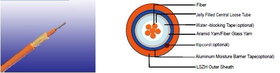
Fibers: Singlemode and multimode fibers, with loose tube technology.
Structure: Central loose tube cable contains one tube with 2-24 single or multimode fibers, which
are filled with water blocking gel.
Water blocking: The jelly filled tube is waterblocked by using swellable tape and thread.
Reinforcement: Either aramid yarn or fiber glass is wound around the tube to provide physical
protection and tensile strength, with added fire protection.
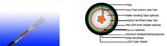
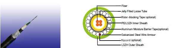
Inner sheath (optional): The cable can be jacketed with either PE or thermoplastic LSZH inner
sheath. PE is the preferred option in outdoor environment for water protection purpose.
Moisture Barrier Tape (optional): An aluminum moisture tape can be incorporated under the sheath
for water blocking and shielding purpose.
Armouring(optional):
For diect burial, either galvanized steel wire braid, corrugated steel tape armour or galvanized
steel wire armour is applied over an inner polyethylene or LSZH sheath. For steel tape armour, the
0.15mm thick steel tape is coated with a copolymer and applied with an overlap. For steel wire braid
or armour, single layer of galvanized steel wire braid or armour is applied.Ripcord (optional): An optional ripcord can be located under the jacket to facilitate jacket removal.
Outer Sheath: Thermoplastic LSZH compound type LTS3 as per BS 7655-6.1(Thermosetting LSZH
compound type SW2-SW4 as per BS 7655-2.6 can be offered.)
Fiber colour code
Fiber colour code |
1 |
Red |
7 |
Brown |
|
2 |
Green |
8 |
Violet |
|
3 |
Blue |
9 |
Turquoise |
|
4 |
Yellow |
10 |
Black |
|
5 |
White |
11 |
Orange |
|
6 |
Grey |
12 |
Pink |
Physical AND THERMAL PROPERTIES
Temperature range during operation (fixed state): -20°C - +60°C
Temperature range during installation (mobile state): 0°C - +50°C
Minimum bending radius: 10 times the outer diameter for unarmoured cables
20 times the outer diameter for armoured cables
CONSTRUCTION
Unarmoured type
CONSTRUCTION PARAMETERS
Cable Code |
Fiber
Count |
Tube
Diameter |
Nominal Overall Diameter |
Approx. Weight |
Tension load |
Crush |
|
(n°) |
mm |
mm |
kg/km |
N |
N/100mm |
CLA-B-C-H-J |
02-06 |
2.7 |
8.0 |
70 |
1000 |
1500 |
CLA-B-C-H-J |
08-16 |
3.5 |
9.0 |
90 |
1200 |
1500 |
CLA-B-C-H-J |
18-24 |
4.2 |
10.0 |
100 |
1500 |
1500 |
Steel Wire Braid
CONSTRUCTION PARAMETERS
Cable Code |
Fiber
Count |
Tube
Diameter |
Nominal Overall Diameter |
Approx. Weight |
Tension load |
Crush |
|
(n°) |
mm |
mm |
kg/km |
N |
N/100mm |
CLA-B-C-2Y(SWB)H-J |
02-06 |
2.7 |
11.5 |
160 |
1000 |
2000 |
CLA-B-C-2Y(SWB)H-J |
08-16 |
3.5 |
12.0 |
180 |
1200 |
2000 |
CLA-B-C-2Y(SWB)H-J |
18-24 |
4.2 |
13.0 |
200 |
1500 |
2000 |
Corrugated Steel Tape Armour

CONSTRUCTION PARAMETERS
Cable Code |
Fiber
Count |
Tube
Diameter |
Diameter |
Approx. Weight |
Tension load |
Crush |
|
(n°) |
mm |
mm |
kg/km |
N |
N/100mm |
CLA-B-C-2Y(STA)H-J |
02-06 |
2.7 |
13.0 |
200 |
1000 |
2500 |
CLA-B-C-2Y(STA)H-J |
08-16 |
3.5 |
14.0 |
220 |
1200 |
2500 |
CLA-B-C-2Y(STA)H-J |
18-24 |
4.2 |
14.5 |
250 |
1500 |
2500 |
Steel Wire armour
CONSTRUCTION PARAMETERS
Cable Code |
Fiber
Count |
Tube
Diameter |
Nominal Overall Diameter |
Approx. Weight |
Tension load |
Crush |
|
(n°) |
mm |
mm |
kg/km |
N |
N/100mm |
CLA-B-C-2Y(SWA)H-J |
02-12 |
2.7 |
10.5 |
180 |
2500 |
4000 |
CLA-B-C-2Y(SWA)H-J |
16-24 |
3.5 |
11.0 |
210 |
2500 |
4000 |
Physical AND THERMAL PROPERTIES
Temperature range during operation (fixed state): -20°C - +60°C
Temperature range during installation (mobile state): 0°C - +50°C
Minimum operation Bending Radius: 10 times the outer diameter for unarmoured cables
20 times the outer diameter for armoured cables
Minimum Installation Bending Radius: 20 times the outer diameter
MECHANICAL PROPERTIES
maximum Compressive Load |
4000N for unarmoured cables
5000N for armoured cables |
Repeated Impact: |
4.4 N.m (J) |
Twist (Torsion): |
180×10 times, 125×OD |
Cyclic Flexing: |
25 cycles for armoured cables;
100 cycles for unarmoured cables. |
Crush Resistance: |
263N/cm (150lb/in) |
Fiber Compliance
Temperature Cycling |
IEC60794-1-2-F2 |
Tensile Strength |
IEC60794-1-2-E1A |
Crush |
IEC60794-1-2-E3 |
Impact |
IEC60794-1-2-E4 |
Repeated Bending |
IEC60794-1-2-E6 |
Torsion |
IEC60794-1-2-E7 |
Kink |
IEC60794-1-2-E10 |
Cable Bend |
IEC60794-1-2-E11 |
Cool Bend |
IEC60794-1-2-E11 |
|