|
 |
Cavo per Materiale Rotabile |
 |
 |
|
 Cavo per Materiale Rotabile Cavo per Materiale Rotabile
FIREROL FRL-MW-3S/FRL-MW-6S 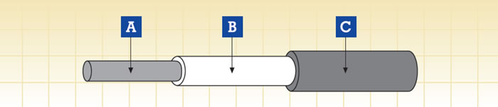
A.Conduttore B.Isolamento C.Guaina
Applicazione
-Used as power and control cable for protected installations inside and outside of rail and transport vehicles, where handling and installation cost are an important factor.
-Used in control, auxillary and main circuit wiring such as cable harnesses, switchboards and control panels, driver desks etc.
Edilizia
Conduttore
Flexible tinned annealed copper wires, stranded as per HD 383 (IEC 60228) class 5
Isolamento
LSZH elastomeric compound as defined in EN 50264-1 (EI 106 to EI 109)
Guaina
LSZH elastomeric compound as defined in EN 50264-1 (EM 101 to EM 104)
Electrical & Mechanical Properties
| Nominal Voltage |
1.8/3 kV or 3.6/6 kV |
| Maximum Conductor Temperature |
+90 deg (fixed installation) |
| Minimum Permissible Ambient Temperature |
-25/-40 deg (fixed installation) |
| Bending Radius |
3 x Overall Diameter (D<12mm); |
| |
4 x Overall Diameter (D>12mm) |
Chemical & Environmental Properties
| EN 60684-2 |
No fluorine |
| EN 50305; EN 60811-2-1 |
Resistance to oil & fuel |
| EN 50305 |
Resistance to ozone |
Fire Performance for rolling stock application
| EN 50306-2 |
Hazard levels HL1, HL2/HL3, HL4 |
| DIN 5510-2 |
Protection level 1/2/3/4 |
| BS 6853 |
Interior use 1a, 1b, II; Exterior use 1a, 1b, II |
| NF F 16-101 |
FO |
Fire Performance in general
| EN 50265-2-1; IEC 60332-1; BS 4066-1 |
Vertical flame propogation for a single insulated wire or cable |
| EN 50266-2-4 + EN 50305; IEC 60332-3C; |
Fire propagation of bunched wires and cables; |
| VDE 0472 Teil 804; BS 4066-3; NFC 32070 |
|
| EN 50268-2; IEC 61034-2; VDE 0472 Teil 816 |
Smoke density |
| EN 50267-2-1; IEC 60754-1; VDE 0472 Teil 815 |
Halogen Free |
| EN 50267-2-2/3; IEC 60754-2; VDE 0472 Teil 813 |
Corrosivity of gases (Acidity & Conductivity) |
| EN 50305; NFX 70-100; NFF 63808; TM1-04; BS6853 |
Toxicity index |
| NFF 16101; NFF 63808; BS6853 |
Smoke index |
FRL-MW-3S 1.8/3 kV
NOMINALCROSS-SECTIONAL AREA
(a) |
CONDUCTOR DIAMETER (a) |
MIN.
MEAN THICKNESS OF INSULATION |
SHEATH NOMINAL THICKNESS MIN. |
OVERALL DIAMETER MIN. |
OVERALL DIAMETER MAX. |
WEIGHT |
COND
UCTOR RESIST
ANCEAT
+20°C |
INSULATION RESISTANCE AT +20°C |
INSULATION RESISTANCE AT +90°C |
|
max |
min |
min |
mm2 |
mm |
mm |
mm |
mm |
mm |
Kg/km |
Ω/km |
MΩ·km |
MΩ·km |
1.5 |
1.5 |
1.3 |
0.8 |
5.7 |
6.7 |
60 |
13.7 |
21.8 |
0.218 |
2.5 |
1.95 |
1.3 |
0.8 |
6.0 |
7.0 |
70 |
8.21 |
18.8 |
0.188 |
4 |
2.5 |
1.3 |
0.8 |
6.5 |
7.6 |
90 |
5.09 |
16.2 |
0.162 |
6 |
3.0 |
1.3 |
0.8 |
7.0 |
8.1 |
110 |
3.39 |
14.4 |
0.144 |
10 |
3.9 |
1.5 |
0.8 |
8.2 |
9.6 |
170 |
1.95 |
12.8 |
0.128 |
16 |
5.0 |
1.5 |
0.8 |
9.2 |
10.8 |
240 |
1.24 |
10.7 |
0.107 |
25 |
6.4 |
1.8 |
1.0 |
11.5 |
13.4 |
350 |
0.795 |
10.3 |
0.103 |
35 |
7.7 |
1.8 |
1.0 |
12.7 |
14.9 |
450 |
0.565 |
8.9 |
0.089 |
50 |
9.2 |
1.8 |
1.0 |
14.1 |
16.5 |
590 |
0.393 |
7.8 |
0.078 |
70 |
11.0 |
1.8 |
1.0 |
15.8 |
18.5 |
790 |
0.277 |
6.7 |
0.067 |
95 |
12.5 |
2.2 |
1.0 |
18.0 |
21.0 |
1050 |
0.210 |
6.5 |
0.065 |
120 |
14.2 |
2.2 |
1.0 |
19.6 |
22.9 |
1270 |
0.164 |
6.1 |
0.061 |
150 |
15.8 |
2.2 |
1.2 |
21.4 |
25.1 |
1590 |
0.132 |
5.8 |
0.058 |
185 |
17.5 |
2.4 |
1.2 |
23.4 |
27.4 |
1900 |
0.108 |
5.6 |
0.056 |
240 |
20.1 |
2.4 |
1.2 |
25.9 |
30.3 |
2490 |
0.0817 |
5.0 |
0.050 |
300 |
22.5 |
2.4 |
1.2 |
28.1 |
32.9 |
3010 |
0.0654 |
4.5 |
0.045 |
400 |
25.8 |
2.6 |
1.4 |
32.0 |
37.4 |
3980 |
0.0495 |
4.4 |
0.044 |
FRL-MW-6S 3.6/6KV
NOMINALCROSS-SECTIONAL AREA |
CONDUCTOR DIAMETER (a) |
MIN.
MEAN THICKNESS OF INSULATION |
SHEATH NOMINAL THICK
NESS MIN. |
OVERALL DIAMETER MIN. |
OVERALL DIAMETER MAX. |
WEIGHT |
CONDUCTOR RESIST
ANCEAT +20°C |
INSULATION RESISTANCE AT +20°C |
INSULATION RESISTANCE AT +90°C |
|
max |
min |
min |
mm2 |
mm |
mm |
mm |
mm |
mm |
Kg/km |
Ω/km |
MΩ·km |
MΩ·km |
2.5 |
1.95 |
2.6 |
0.8 |
8.6 |
10.1 |
120 |
8.21 |
24.6 |
0.246 |
4 |
2.5 |
2.6 |
0.8 |
9.1 |
10.7 |
140 |
5.09 |
21.6 |
0.216 |
6 |
3.0 |
2.6 |
0.8 |
9.6 |
11.2 |
165 |
3.39 |
19.5 |
0.195 |
10 |
3.9 |
2.6 |
0.8 |
10.4 |
12.2 |
220 |
1.95 |
16.7 |
0.167 |
16 |
5.0 |
2.6 |
0.8 |
11.5 |
13.4 |
290 |
1.24 |
14.2 |
0.142 |
25 |
6.4 |
2.9 |
1.0 |
13.7 |
16.1 |
430 |
0.795 |
13.1 |
0.131 |
35 |
7.7 |
2.9 |
1.0 |
14.9 |
17.5 |
540 |
0.565 |
11.6 |
0.116 |
50 |
9.2 |
2.9 |
1.0 |
16.4 |
19.1 |
670 |
0.393 |
10.2 |
0.102 |
70 |
11.0 |
2.9 |
1.0 |
18.0 |
21.1 |
880 |
0.277 |
8.9 |
0.089 |
95 |
12.5 |
2.9 |
1.0 |
19.5 |
22.8 |
1100 |
0.210 |
8.0 |
0.080 |
120 |
14.2 |
2.9 |
1.2 |
21.4 |
25.1 |
1380 |
0.164 |
7.5 |
0.075 |
150 |
15.8 |
2.9 |
1.2 |
22.9 |
26.8 |
1660 |
0.132 |
6.9 |
0.069 |
185 |
17.5 |
3.2 |
1.2 |
25.1 |
29.4 |
2010 |
0.108 |
6.7 |
0.067 |
240 |
20.1 |
3.4 |
1.4 |
28.3 |
33.1 |
2670 |
0.0817 |
6.4 |
0.064 |
300 |
22.5 |
3.4 |
1.4 |
30.6 |
35.8 |
3170 |
0.0654 |
5.9 |
0.059 |
400 |
25.8 |
3.4 |
1.4 |
33.7 |
39.4 |
4150 |
0.0495 |
5.2 |
0.052 |
(a)= For information,indicative only
|